EasyManua.ls Logo

Delta DVP-PLC User Manual

Delta DVP-PLC
586 pages
To Next Page IconTo Next Page
To Previous Page IconTo Previous Page
Page #429 background imageLoading...
Page #429 background image
8 Application Instructions API 100-149
DVP-PLC Application Manual
8-27
API
Mnemonic Operands Function
117
D DEG P
Radian Angle
Controllers
ES/EX/SS SA/SX/SC EH/SV
Bit Devices Word Devices Program Steps Type
OP
X Y M S K H KnX KnY KnM KnS T C D E F
S * * *
D *
DDEG, DDEGP: 9 steps
PULSE 16-bit 32-bit
ES EX SS SA SX SC EH SV ES EX SS SA SX SC EH SV ES EX SS SA SX SC EH SV
Operands:
S: Source (radian) D: Result (angle)
Explanations:
1. See the specifications of each model for their range of use.
2. Flags: M1020 (zero flag); M1021 (borrow flag); M1022 (carry flag)
3. Degree = radian × (180/
π)
4. If the absolute value of the resultmaximum floating point available, the carry flag M1022 = On.
5. If the absolute value of the resultminimum floating point available, the borrow flag M1021 = On.
6. If the result = 0, the zero flag M1020 = On.
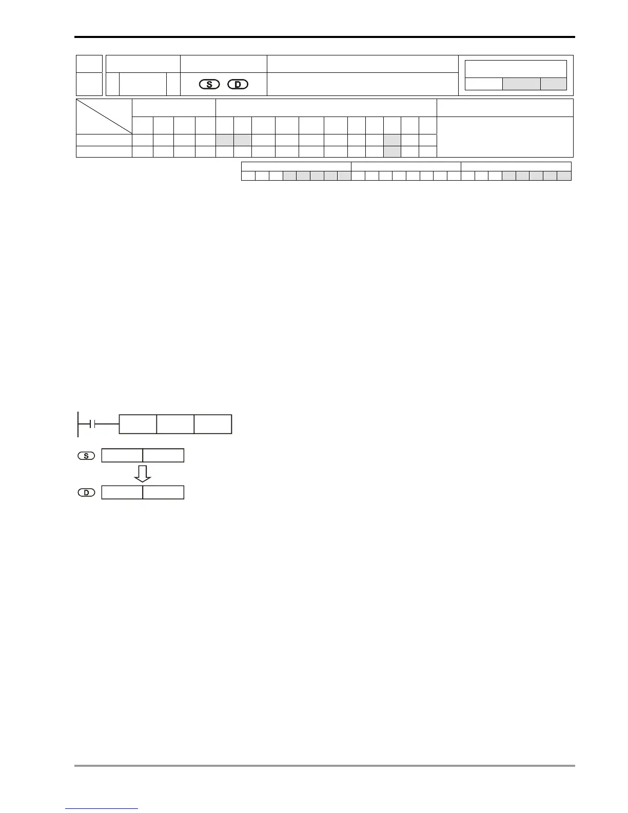
Program Example:
When X0 = On, designate the angle of binary floating point (D1, D0). Convert the radian into angle and store the
result in binary floating point in (D11, D10).
X0
DDEG D0 D10
D 1 D 0
D 11 D 10
binary floating point
Angle (radian 180/ )
X
π
Radian
binary floating point
Remarks:
For floating point operations, see “5.3 Handling of Numeric Values”.

Table of Contents

Question and Answer IconNeed help?

Do you have a question about the Delta DVP-PLC and is the answer not in the manual?

Delta DVP-PLC Specifications

General IconGeneral
ManufacturerDelta Electronics
ModelDVP-PLC
CategoryController
Humidity5% to 95% RH, non-condensing
Programming LanguageLadder Diagram (LD), Instruction List (IL), Sequential Function Chart (SFC)
CPU TypeVarious, depending on the specific model within the DVP series (e.g., ES2, EX2, SX2, SA2, EH3, etc.)
Operating TemperatureTypically 0°C to 55°C (32°F to 131°F)
Storage TemperatureTypically -25°C to 70°C (-13°F to 158°F)

Summary

1 Basic Principles of PLC Ladder Diagram

Foreword: Background and Functions of PLC

Overview of PLC technology, its history, and purpose in industrial automation.

1.1 The Working Principles of Ladder Diagram

Explains the fundamental concepts and building blocks of PLC ladder diagrams.

1.2 Differences Between Traditional Ladder Diagram and PLC Ladder Diagram

Highlights the distinctions between traditional relay logic and PLC ladder diagram representations.

1.3 How to Edit Ladder Diagram

Details the process of creating and editing ladder diagrams, including symbols and logic.

1.4 How to Edit a PLC Ladder Diagram

Covers the practical steps and considerations for editing PLC ladder programs using software.

1.5 The Conversion of PLC Command and Each Diagram Structure

Explains how PLC commands are converted into ladder diagram structures.

1.6 Simplified Ladder Diagram

Demonstrates techniques for simplifying ladder diagrams for better readability and efficiency.

1.7 Basic Program Designing Examples

Provides practical examples of designing basic PLC programs using ladder logic.

Frequently Used Control Circuits

Illustrates common control circuits implemented using ladder diagrams, such as latched circuits and interlocks.

2 Functions of Devices in DVP-PLC

2.1 All Devices in DVP-PLC

Comprehensive overview of all available devices, their types, ranges, and functions in DVP-PLC systems.

2.2 Values, Constants [K] / [H]

Explanation of how decimal (K) and hexadecimal (H) values are used as constants in PLC operations.

2.3 External Input/Output Contacts [X] / [Y]

Details the numbering and functions of external input (X) and output (Y) contacts across various MPU models.

2.4 Auxiliary Relays [M]

Describes the numbering, types, and functions of auxiliary relays (M) used for internal logic and control.

2.5 Step Relays [S]

Explains the numbering, types, and functions of step relays (S), crucial for sequential control and SFC.

2.6 Timers [T]

Details the various types of timers (T) and their functions, including timing units and contacts.

2.7 Counters [C]

Covers the different types of counters (C), their numbering, and functions for counting operations.

2.8 Registers [D], [E], [F]

Explains data registers (D) for value storage and index registers (E, F) for indirect addressing.

2.9 Pointer [N], [P], Interruption Pointer [I]

Describes pointer instructions used for program flow control, subroutines, and interruption handling.

2.10 Special Auxiliary Relays and Data Registers

Lists and explains the specific functions of special M relays and D data registers.

2.11 Functions of Special Auxiliary Relays and Data Registers

Provides detailed explanations of the functions of special M relays and D registers.

3 Basic Instructions

3.1 Basic Instructions and Step Ladder Instructions

Introduces fundamental PLC instructions like LD, LDI, AND, OR, and step ladder instructions STL, RET.

3.2 Explanations on Basic Instructions

Detailed explanations and examples for basic instructions used in PLC programming.

4 Step Ladder Instructions

4.1 Step Ladder Instructions [STL], [RET]

Details the STL and RET instructions for creating step ladder diagrams and controlling program flow.

4.2 Sequential Function Chart (SFC)

Explains Sequential Function Charts (SFC) as a graphical method for designing sequential control.

4.3 How does a Step Ladder Instruction Work?

Describes the operational principles and execution flow of step ladder instructions.

4.4 Things to Note for Designing a Step Ladder Program

Provides essential considerations and best practices for designing effective step ladder programs.

4.5 Types of Sequences

Explains different types of sequences, including single, multiple, and divergent/convergent sequences.

4.6 IST Instruction

Details the IST instruction for setting initial states and managing step ladder control procedures.

5 Categories & Use of Application Instructions

5.1 List of Instructions

A comprehensive list of all application instructions, categorized by function.

5.2 Composition of Application Instruction

Explains the structure of application instructions, including mnemonic, operands, and controllers.

5.3 Handling of Numeric Values

Covers the handling of numeric values, including binary, decimal, and floating-point representations.

5.4 E, F Index Register Modification

Explains the usage of index registers E and F for modifying operands and accessing data.

5.5 Instruction Index

An index to quickly locate application instructions based on their API number and mnemonic.

6 Application Instructions API 00-49

6.1 Loop Control (API 00-09)

Instructions for controlling program loops, such as CJ, CALL, and FOR/NEXT.

6.2 Transmission Comparison (API 10-19)

Instructions related to data comparison and transmission, including MOV, CMP, and ZCP.

6.3 Four Arithmetic Operation (API 20-29)

Instructions for basic arithmetic operations like ADD, SUB, MUL, and DIV.

6.4 Rotation & Displacement (API 30-39)

Instructions for bit and word shifting operations, including ROR, ROL, and WSFR.

6.5 Data Processing (API 40-54)

Instructions for various data manipulation tasks like SUM, MEAN, and square root.

6.6 High Speed Processing (API 53-54)

Instructions for high-speed counter operations and comparisons, such as DHSCS, DHSCR, and DHSZ.

7 Application Instructions API 50-99

7.1 List of Instructions

A list of application instructions within the API 50-99 range, categorized by function.

7.2 Composition of Application Instruction

Explains the structure of application instructions, including mnemonic, operands, and controllers.

7.3 Handling of Numeric Values

Details how numeric values like constants and registers are handled in PLC operations.

7.4 E, F Index Register Modification

Explains the usage of index registers E and F for modifying operands and accessing data.

7.5 Instruction Index

An index to quickly locate application instructions based on their API number and mnemonic.

8 Application Instructions API 100-149

100 MODRD P

Instruction for reading Modbus data from peripheral devices using ASCII or RTU mode.

101 MODWR P

Instruction for writing Modbus data to peripheral devices using ASCII or RTU mode.

102 FWD P

Instruction for controlling forward running of VFD-A drives.

103 REV P

Instruction for controlling reverse running of VFD-A drives.

104 STOP P

Instruction for stopping VFD-A drives.

105 RDST P

Instruction to read the status of VFD-A drives.

106 RSTEF P

Instruction to reset abnormal conditions in VFD-A series AC motor drives.

107 CRC P

Instruction for performing CRC checksum calculations for communication protocols.

110 D DECMP P

Instruction for floating-point comparison operations.

111 D EZCP P

Instruction for floating-point zone comparison operations.

112 D MOVR P

Instruction to move floating-point data between registers.

116 D RAD P

Instruction to convert angles from degrees to radians.

117 D DEG P

Instruction to convert radians to angles in degrees.

118 D EBCD P

Instruction for converting binary floating-point values to decimal floating-point.

119 D EBIN P

Instruction for converting decimal floating-point values to binary floating-point.

120 D EADD P

Instruction for performing floating-point addition.

121 D ESUB P

Instruction for performing floating-point subtraction.

122 D EMUL P

Instruction for performing floating-point multiplication.

123 D EDIV P

Instruction for performing floating-point division.

9 Application Instructions API 150-199

150 MODRW P

Instruction for reading/writing Modbus data for communication.

151 PWD P

Instruction for detecting the pulse width of input signals.

152 RTMU P

Instruction to start the measurement of execution time for interruption.

153 RTMD P

Instruction to end the measurement of execution time for interruption.

154 RAND P

Instruction to generate random numbers within a specified range.

155 D ABSD P

Instruction for absolute control of multiple output pulses.

156 D ZRN P

Instruction for zero return operation, used to move axes to a zero point.

157 D PLSV P

Instruction for adjustable speed pulse output.

158 D DRVI P

Instruction for driving to increment/decrement based on pulse count.

159 D DPPMA P

Instruction for 2-axis relative point-to-point motion control.

160 TCMP P

Instruction for comparing time values from the RTC.

161 TZCP P

Instruction for comparing time zones based on RTC values.

162 TADD P

Instruction for adding time values (hour, minute, second).

163 TSUB P

Instruction for subtracting time values (hour, minute, second).

166 TRD P

Instruction to read the current time from the RTC.

167 TWR P

Instruction to write the current time to the RTC.

169 D HOUR P

Instruction to measure and store time in hours.

170 D GRY P

Instruction to convert BIN value to Gray code.

171 D GBIN P

Instruction to convert Gray code to BIN value.

172 D ADDR P

Instruction for floating-point addition.

173 D SUBR P

Instruction for floating-point subtraction.

174 D MULR P

Instruction for floating-point multiplication.

175 D DIVR P

Instruction for floating-point division.

10 Application Instructions API 200-249

202 SCAL P

Instruction to calculate proportional values using slope and offset.

203 D SCLP P

Instruction for parameter proportional value calculation.

215~223 D LD※

Instructions for contact logical operations (AND, OR, XOR) on parallel contacts.

224~230 D AND※

Instructions for logical AND comparison between two data sources.

221~223 D OR※

Instructions for logical OR comparison between two data sources.

Related product manuals