7 Application Instructions API 50-99
DVP-PLC APPLICATION MANUAL
7-98
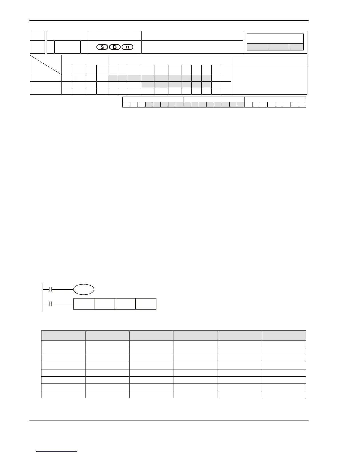
API Mnemonic Operands Function
83
HEX P
Converts ASCII to Hex
Controllers
ES/EX/SS SA/SX/SC EH/SV
Bit Devices Word Devices Program Steps Type
OP
X Y M S K H KnX KnY KnM KnS T C D E F
S * * * * * * * * *
D * * * * * *
n * *
HEX, HEXP: 7 steps
PULSE 16-bit 32-bit
ES EX SS SA SX SC EH SV ES EX SS SA SX SC EH SV ES EX SS SA SX SC EH SV
Operands:
S: Start device for source data D: Start device for storing the converted result n: Number of bits to be converted
Explanations:
1. Range of n: 1 ~ 256
2. See the specifications of each model for their range of use.
3. Flag: M1161 (8/16 bit mode switch)
4. 16-bit conversion mode: When M1161 = Off, the instruction is in 16-bit conversion mode. ASCII codes of the 8
high bits and 8 low bits of the hex data in S are converted into hex value and sent to D (every 4 bits as a group). n
= the number of bits converted into ASCII codes.
5. 8-bit conversion mode: When M1161 = On, the instruction is in 8-bit conversion mode. Every bit of the hex data in
S are converted into ASCII codes and sent to the 8 low bits of D. n = the number of converted bits. (All 8 high bits
of D = 0)
Program Example 1:
1. M1161 = Off: The 16-bit conversion mode
2. When X0 = On, convert the ASCII codes stored in the registers starting from D20 into hex value and send the
result (every 4 bits as a group) to registers starting from D10. n = 4.
X0
HEX D20 D10 K4
M1001
M1161
3. Assume
S
ASCII code Converted to hex
S
ASCII code Converted to hex
D20 low byte H 43 “C” D24 low byte H 34 “4”
D20 high byte H 44 “D” D24 high byte H 35 “5”
D21 low byte H 45 “E” D25 low byte H 36 “6”
D21 high byte H 46 “F” D25 high byte H 37 “7”
D22 low byte H 38 “8” D26 low byte H 30 “0”
D22 high byte H 39 “9” D26 high byte H 31 “1”
D23 low byte H 41 “A” D27 low byte H 32 “2”
D23 high byte H 42 “B” D27 high byte H 33 “3”
4. When n = 4, the bit structure will be as:
 Loading...


