7 Application Instructions API 50-99
DVP-PLC APPLICATION MANUAL
7-39
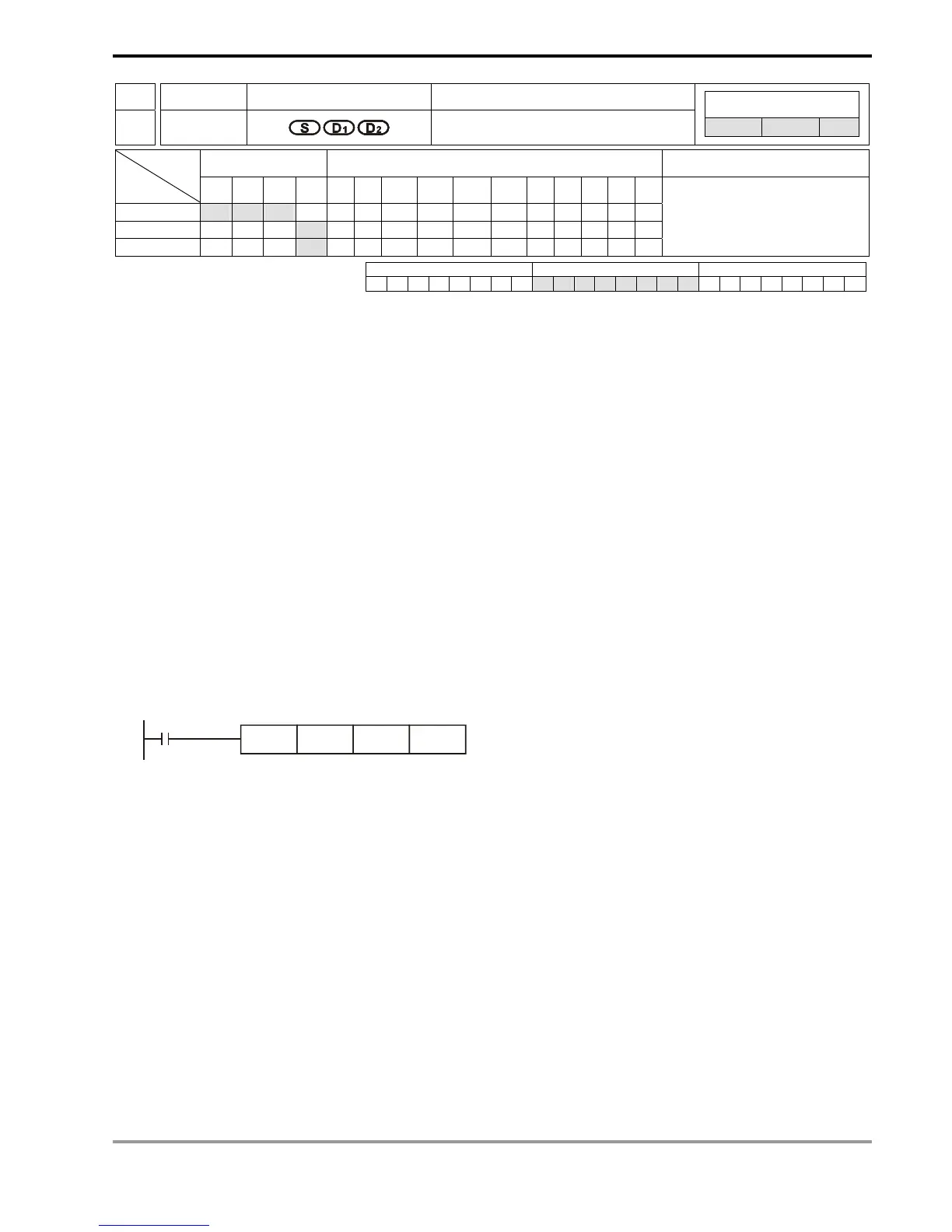
API Mnemonic Operands Function
60
IST
Initial State
Controllers
ES/EX/SS SA/SX/SC EH/SV
Bit Devices Word Devices Program Steps Type
OP
X Y M S K H KnX KnY KnM KnS T C D E F
S
* * *
D
1
*
D
2
*
IST: 7 steps
PULSE 16-bit 32-bit
ES EX SS SA SX SC EH SV ES EX SS SA SX SC EH SV ES EX SS SA SX SC EH SV
Operands:
S: Start device in the designated operation mode D
1
: The smallest No. of designated step in auto mode
D
2
: The biggest No. of designated step in auto mode
Explanations:
1. S will occupy 8 consecutive points.
2. Range of D
1
and D
2
: for SA/SX/SC/EH/EH2/SV S20 ~ S899; for ES/EX/SS S20 ~ S127; D
2
> D
1
.
3. See the specifications of each model for their range of use.
4. ES/SA series MPU does not support E, F index register modification.
5. IST instruction can only be used once in the program.
6. Flags: M1040 ~ M1047. See remarks for more details.
7. IST instruction is a handy instruction specifically for the initial status of step ladder control procedure to
accommodate special auxiliary relay.
Program Example 1:
1. Use of IST instruction
M1000
IST X10 S20 S60
S
X10: Individual operation
X11: Zero return
X12: Step operation
X13: One cycle operation
X14: Continuous operation
X15: Zero return enabled switch
X16: Start switch
X17: Stop switch
2. When IST instruction is being executed, the following special auxiliary relays will switch automatically.
M1040: Operation forbidden
M1041: Operation starts
M1042: Pulse output enabled
M1047: STL monitor enabled
S0: Initiates manual operation
S1: Initiates zero return
S2: Initiates auto operation
3. S10 ~ S19 are for zero return and cannot be used as general steps. When S0 ~ S9 are in use, S0 ~ S2 represent
manual operation mode, zero return mode and auto operation mode. Therefore, in the program , you have to
write the circuit of the three steps in advance.
4. When switched to S1 (zero return) mode, any On in S10 ~ S19 will result in no zero return.
5. When switched to S2 (auto operation) mode, any On of the S in D
1
~ D
2
or M1043 = On will result in no auto
operation.

 Loading...


