7 Application Instructions API 50-99
DVP-PLC APPLICATION MANUAL
7-101
API Mnemonic Operands Function
84
CCD P
Check Code
Controllers
ES/EX/SS SA/SX/SC EH/SV
Bit Devices Word Devices Program Steps Type
OP
X Y M S K H KnX KnY KnM KnS T C D E F
S * * * * * * *
D * * * * *
n * * *
CCD, CCDP: 7 steps
PULSE 16-bit 32-bit
ES EX SS SA SX SC EH SV ES EX SS SA SX SC EH SV ES EX SS SA SX SC EH SV
Operands:
S: Start device for source data D: Device for storing the sum check result n: Number of data
Explanations:
1. Range of n: 1 ~ 256
2. See the specifications of each model for their range of use.
3. Flag: M1161 (8/16 bit mode switch)
4. The sum check is used for ensuring the correctness of the data transmission.
5. 16-bit conversion mode: When M1161 = Off, the instruction is in 16-bit conversion mode. The instruction sums
up n data (8 bits as a unit) from the start register designated in S and stores the results in the registers
designated in D. The parity bits are stored in D + 1.
6. 8-bit conversion mode: When M1161 = On, the instruction is in 8-bit conversion mode. The instruction sums up n
data (8 bits as a unit; only 8 low bits are valid) from the start register designated in S and stores the results in the
registers designated in D. The parity bits are stored in D + 1.
Program Example 1:
1. M1161 = Off: The 16-bit conversion mode
2. When X0 = On, the instruction will sum up 6 data stored in the register designated in D0 (8 bits as a unit; n = 6
indicates D0 ~ D2 are designated) and store the result in the register designated in D100. The parity bits are
stored in D101.
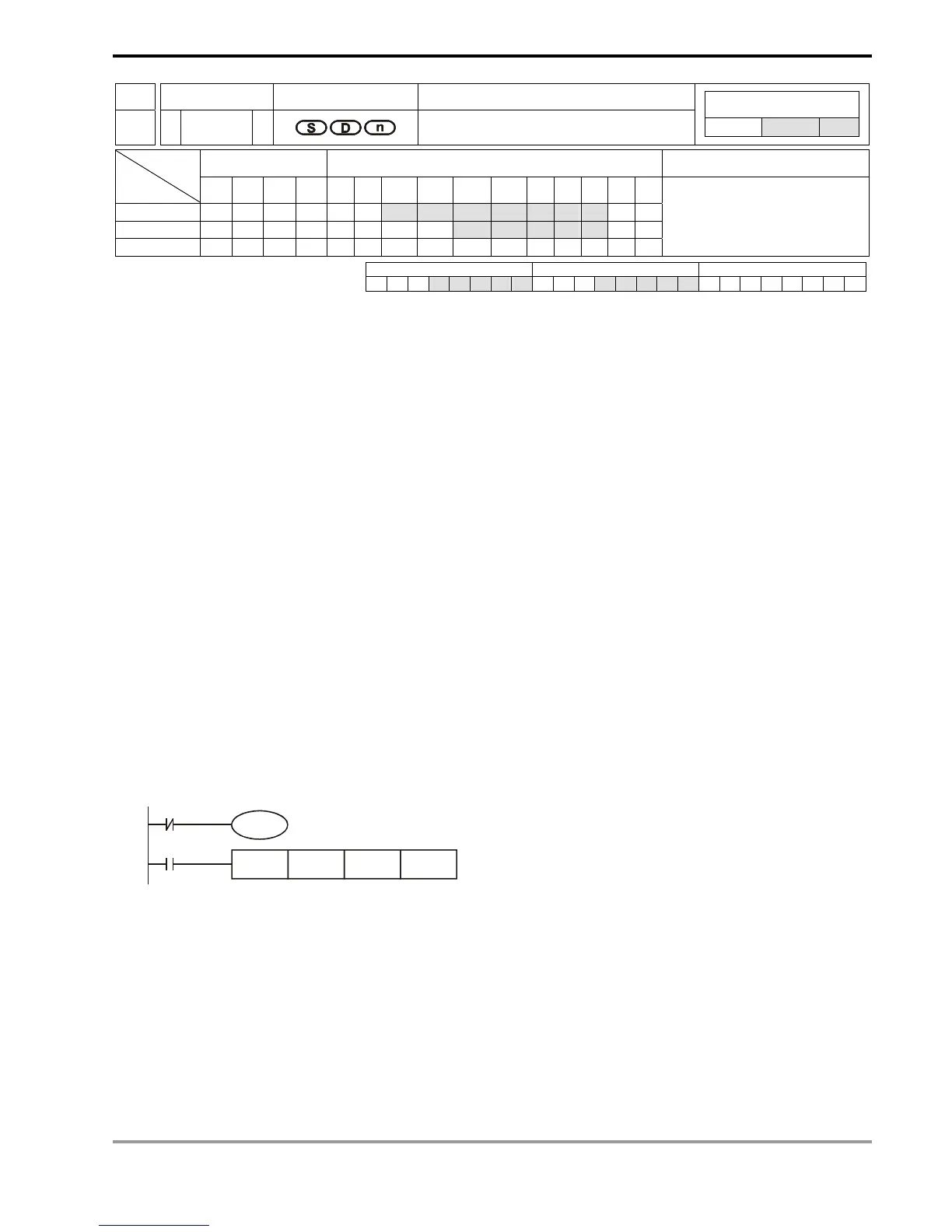
X0
CCD D0 D100 K6
M1000
M1161