7 Application Instructions API 50-99
DVP-PLC APPLICATION MANUAL
7-94
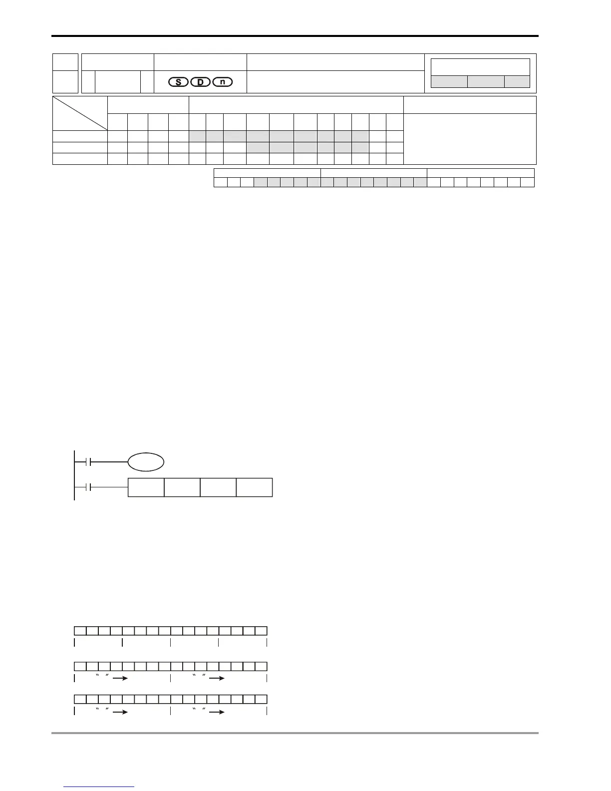
API Mnemonic Operands Function
82
ASCI P
Converts Hex to ASCII
Controllers
ES/EX/SS SA/SX/SC EH/SV
Bit Devices Word Devices Program Steps Type
OP
X Y M S K H KnX KnY KnM KnS T C D E F
S * * * * * * * * *
D * * * * * *
n * *
ASCI, ASCIP: 7 steps
PULSE 16-bit 32-bit
ES EX SS SA SX SC EH SV ES EX SS SA SX SC EH SV ES EX SS SA SX SC EH SV
Operands:
S: Start device for source data D: Start device for storing the converted result n: Number of bits to be converted
Explanations:
1. Range of n: 1 ~ 256
2. See the specifications of each model for their range of use.
3. Flag: M1161 (8/16 bit mode switch)
4. 16-bit conversion mode: When M1161 = Off, the instruction converts every bit of the hex data in S into ASCII
codes and send them to the 8 high bits and 8 low bits of D. n = the converted number of bits.
5. 8-bit conversion mode: When M1161 = On, the instruction converts every bit of the hex data in S into ASCII
codes and send them to the 8 low bits of D. n = the number of converted bits. (All 8 high bits of D = 0)
Program Example 1:
1. M1161 = Off: The 16-bit conversion mode
2. When X0 = On, convert the 4 hex values in D10 into ASCII codes and send the result to registers starting from
D20.
X0
ASCI D10 D20 K4
M1001
M1161
3. Assume
(D10) = 0123 H ‘0’ = 30H ‘4’ = 34H ‘8’ = 38H
(D11) = 4567 H ‘1’ = 31H ‘5’ = 35H ‘9’ = 39H
(D12) = 89AB H ‘2’ = 32H ‘6’ = 36H ‘A’ = 41H
(D13) = CDEF H ‘3’ = 33H ‘7’ = 37H ‘B’ = 42H
4. When n = 4, the bit structure will be as:
0000000100100011
01
23
D10=0123 H
D20
D21
0011000100110000
0011001100110010
1
31H
0
30H
3
33H
2
32H
High byte
Low byte
High byte
Low byte