6 Application Instructions API 00-49
DVP-PLC Application Manual
6-43
API Mnemonic Operands Function
W
28
D
XOR P
Logical Exclusive OR
Controllers
ES/EX/SS SA/SX/SC EH/SV
Bit Devices Word Devices Program Steps Type
OP
X Y M S K H KnX KnY KnM KnS T C D E F
S
1
* * * * * * * * ***
S
2
* * * * * * * * ***
D
* * * * * ***
WXOR, WXORP: 7 steps
DXOR, DXORP: 13 steps
PULSE 16-bit 32-bit
ES EX SS SA SX SC EH SV ES EX SS SA SX SC EH SV ES EX SS SA SX SC EH SV
Operands:
S
1
: Source data device 1 S
2
: Source data device 2 D: Operation result
Explanations:
1. If S
1
, S
2
and D are used in device F, only 16-bit instruction is applicable.
2. See the specifications of each model for their range of use.
3. This instruction conducts logical XOR operation of S
1
and S
2
and stores the result in D.
4. Operation rule: If the bits in S
1
and S
2
are the same, the corresponding bit of the operation result in D will be “0”;
if the bits in S
1
and S
2
are different, the corresponding bit of the operation result in D will be “1”.
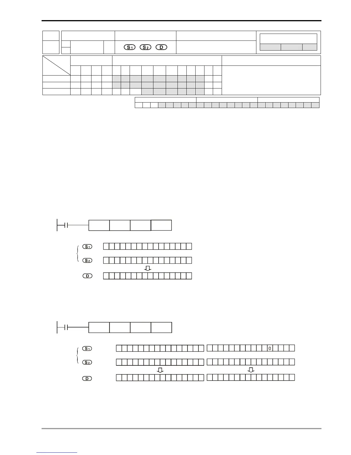
Program Example 1:
When X0 = On, the 16-bit D0 and D2 will perform WXOR, logical XOR operation, and the result will be stored in D4.
X0
WXOR D0 D2
D4
00 111111
000 0 0 011 1 1
00 00
11 0
WOR
b15
0000 0011
0111 0 1
11001111 0
Before
execution
After
execution
D0
D2
D4
b0
Program Example 2:
When X1 = On, the 32-bit (D11, D10) and (D21, D20) will perform DXOR, logical XOR operation, and the result will be
stored in (D41, D40).
X1
DXOR D10 D20
D40
00 111111
000 0 0 001 1 1
11 11
00 0
b31
1111 1100
1000 0
1 11 10 011 1
Before
execution
After
execution
D11 D10
DXOR
1
D21 D20
D41 D40
00 111111
000 0 0 001 1 1
11 11
00 0
b15
1111 110
1000 0
11110011 1
1
b0