9 Application Instructions API 150-199
DVP-PLC Application Manual
9-95
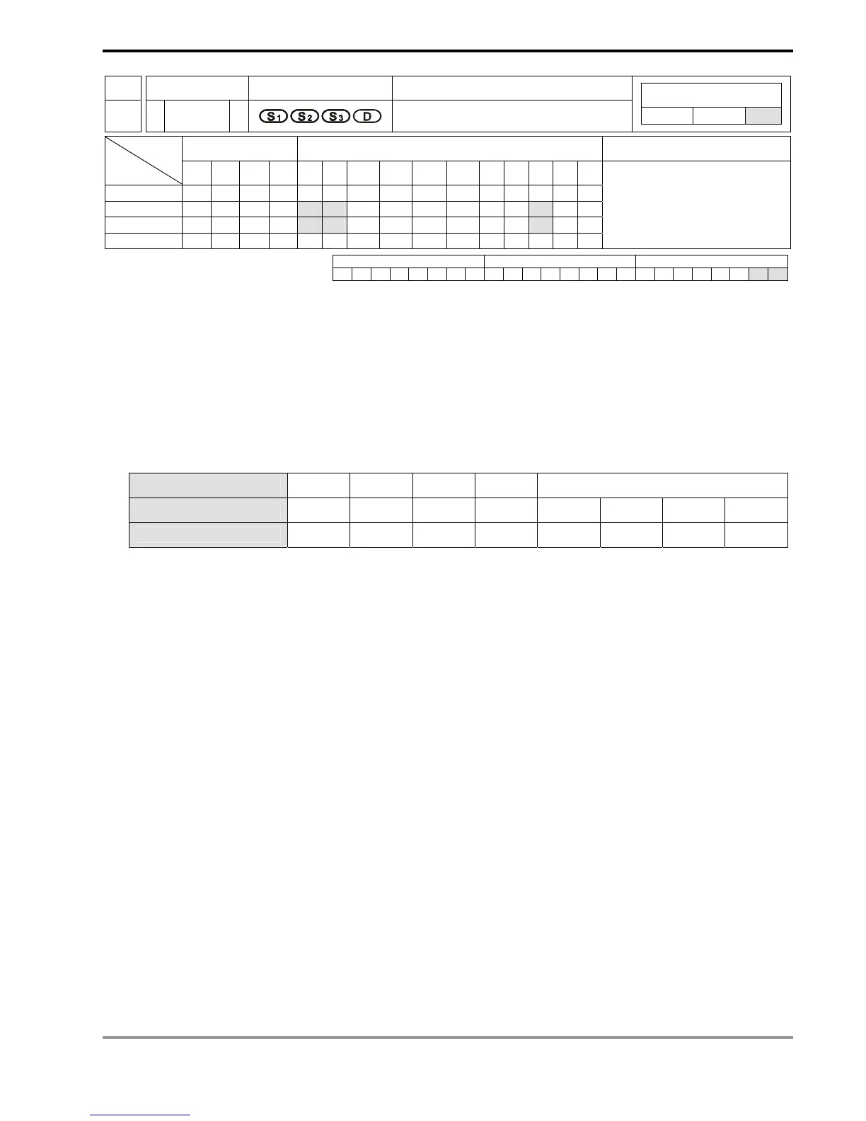
API Mnemonic Operands Function
197
D CLLM
Close Loop Position Control
Controllers
ES/EX/SS SA/SX/SC EH/SV
Bit Devices Word Devices Program Steps Type
OP
X Y M S K H KnX KnY KnM KnS T C D E F
S
1
* *
S
2
* * *
S
3
* * *
D *
DCLLM: 17 steps
PULSE 16-bit 32-bit
ES EX SS SA SX SC EH SV ES EX SS SA SX SC EH SV ES EX SS SA SX SC EH SV
Operands:
S
1
: Feedback source device S
2
: Target number of feedbacks S
3
: Target frequency of output
D: Pulse output device
Explanations:
1. Flags: M1029, M1030, M1334, M1335. See remarks for more details.
2. This instruction only supports EH2/SV series MPU, not EH series.
3. The corresponding interruption of S
1
:
Source device
X0 X1 X2 X3 C241 ~ C254
Corresponding outout
Y0 Y2 Y4 Y6 Y0 Y2 Y4 Y6
Interruption No.
I00 I10 I20 I30 I010 I020 I030 I040
= 1: rising-edige trigger; = 0: falling-edge trigger
a) When S
1
designates X as the input points and the pulse output reaches the set target number of feedbacks
in S
2
, the output will continue to operate by the frequency of the last segment until the interruption of X input
points occurs.
b) When S
1
designates a high speed counter and the pulse output reaches the set target number of feedbacks
in S
2
, the output will continue to operate by the frequency of the last segment until the feedback pulses
reaches the target number.
c) S
1
can be a high speed counter C or an external interruption X. If S
1
is C, DCNT instruction should be first
executed to enable the high-speed counting function and EI and I0x0 interruption service program to enable
the high-speed interruption. If S
1
is X, EI instruction and I0x0 interruption service program should be
executed to enable the external interruption function.
4. The range of S
2
: -2,147,483,648 ~ +2,147,483,647 (+/- represents the forward/backward direction). When in
forward direction, the pulse present value registers CH0 (D1337 high word, D1336 low word), CH1 (D1339 high
word, D1338 low word), CH2 (D1376 high word, D1375 low word) and CH3 (D1378 high word, D1377 low word)
will increase. When in backward direction, the present value will decrease.
5. If S
3
is lower than 10Hz, the output will operate at 10Hz; if S
3
is higher than 200KHz, the output will operate at
200KHz.
6. D can only designate Y0, Y2, Y4 and Y6 and the direction signals repectively are Y1, Y3, Y5 and Y7. When
there is a direction signal output, the direction signal will not be Off immediately after the pulse output is
completed. The direction signal will be Off only when the drive contact is Off.

 Loading...


