4 Step Ladder Instructions
DVP-PLC Application Manual
4-4
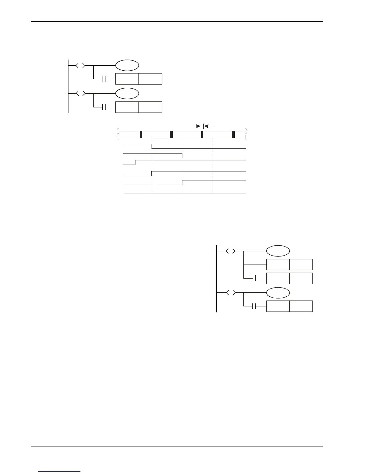
When the status contact Sn = On, the circuit will be activated. When Sn = Off, the circuit will be disactivated. The
actions will delay for 1 scan time.
SET S12
Y11
SET S14
S10
S
X0
S12
S
X1
Y10
Executing the timing diagram below. After the
status of S10 and S12 are transferred (taking place
simultaneously), and after a delay of 1 scan time,
Y10 will be Off and Y11 will be On. There will not be
overlapping outputs.
STL S10
S10
Y10
S12
Y11
X1
X0
Program
execution
Ren ew I nput/ Out put
Circuit not activate d
Program
execution
Program
execution
3. Repeated Use of Output Coil:
a) You can use output coils of the same No. in different steps.
b) See the diagram in the right. There can be the same
output device (Y0) among different statuses. Y0 will be On
when S10 or S20 is On. Such as right diagram, there is the
same output device Y0 in the different state. No matter
S10 or S20 is On, Y0 will be On.
c) Y0 will be Off when S10 is transferring to S20. After S20 is
On, Y0 will output again. Therefore in this case, Y0 will be
On when S10 or S20 is On.
d) Normally in a ladder diagram, avoid repeated use of an
output coil. The No. of output coil used by a step should
also avoid being used when the step ladder diagram
returns to a general ladder diagram.
SET Y1
Y0
SET S20
SET S30
S10
S
X0
S20
S
X1
Y0

 Loading...


