5 Categories & Use of Application Instructions
DVP-PLC Application Manual
5-9
Data processing of word devices combined from bit devices
16-bit instruction 32-bit instruction
Designated value: K-32,768 ~ K32,767
Designated value: K-2,147,483,648 ~ K2,147,483,647
Values for designated K1 ~ K4 Values for designated K1 ~ K8
K1 (4 bits) 0 ~ 15 K1 (4 bits) 0 ~ 15
K2 (8 bits) 0 ~ 255 K2 (8 bits) 0 ~ 255
K3 (12 bits) 0 ~ 4,095 K3 (12 bits) 0 ~ 4,095
K4 (16 bits) -32,768 ~ +32,767 K4 (16 bits) 0 ~ 65,535
K5 (20 bits) 0 ~ 1,048,575
K6 (24 bits) 0 ~ 167,772,165
K7 (28 bits) 0 ~ 268,435,455
K8 (32 bits) -2,147,483,648 ~ +2,147,483,647
Flags
1. General flags
a) The flags listed below are for indicating the operational result of the application instruction.
M1020: zero flag M1022: carry flag
M1021: borrow flag M1029: execution of instruction is completed
All flags will turn On or Off according to the operational result of an instruction. For example, the
execution result of operation instructions ADD/SUB/MUL/DVI will affect the status of M1020 ~ M1022. When
the instruction is not executed, the On/Off status of the flag will be held. The status of the four flags relates to
many instructions. See relevant instructions for more details.
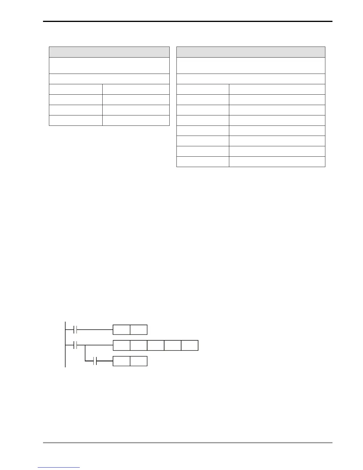
b) Example of M1029
When the contact of DSW (Digital Switch) instruction is On, 4 output points will automatically act in cycle
at the frequency of 0.1 second in order to read the set value of the digital switch. If the contact goes Off
during the execution, the action will be disable. When it is On again, the disabled action will be re-executed. If
you do not wish the action to be disabled, you can take the circuit below as a reference.
X0
SET M0
M0
DSW X10 Y10 D0 K0
RST M0
M1029
When X0 = On, DSW will be enabled.
When X0 = Off, M0 will be Off only when DSW
completes a cycle and M1029 = On.
2. Error Operation Flags
Errors occur during the execution of the instruction when the combination of application instructions is
incorrect or the devices designated by the operand exceed their range. Other than errors, the flags listed in
the table below will be On, and error codes will also appear.

 Loading...


