4 Step Ladder Instructions
DVP-PLC Application Manual
4-11
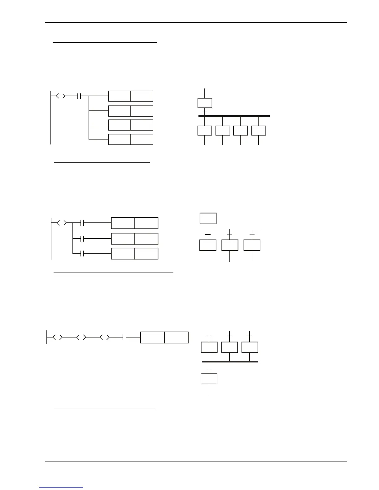
a) Structure of simultaneous divergence
When the condition at the current step is true, the step can be transferred to many steps. See the diagrams
below. When X0 = On, S20 will be simultaneously transferred to S21, S22, S23 and S24.
Ladder diagram:
X0
SET
SET S22
S21
S
SET S23
S20
SET S24
SFC:
S20
S21
S22 S23 S24
b) Structure of alternative divergence
When the individual condition at the current status is true, the step will be transferred to another individual step.
See the diagrams below. When X0 = On, S20 will be transferred to S30; when X1 = On, S20 will be transferred to
S31; when X2 = On, S20 will be transferred to S32.
Ladder diagram:
X0
SET
SET S31
S30
S
SET S32
S20
X1
X2
SFC:
S20
S30
S31 S32
X0 X1 X2
c) Structure of the simultaneous convergence
See the ladder diagram below. A continuous STL instruction represents a simultaneous convergence. When the
condition is true after a continuous output, the step will be transferred to the next step. In the simultaneous
convergence, only when several conditions are true will the transfer be allowed.
Ladder diagram:
X
SET
S50
S
S40
S
S41
S
S42
SFC:
S40
S50
S41 S42
X2
d) Structure of alternative convergence
See the diagrams below. Depending on the condition of the input signal of which of S30, S40 and S50 becomes
true first, the first one will be first transferred to S60.

 Loading...


