7 Application Instructions API 50-99
DVP-PLC APPLICATION MANUAL
7-64
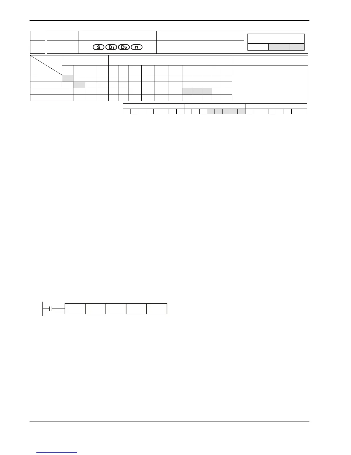
API Mnemonic Operands Function
72
DSW
Digital Switch
Controllers
ES/EX/SS SA/SX/SC EH/SV
Bit Devices Word Devices Program Steps Type
OP
X Y M S K H KnX KnY KnM KnS T C D E F
S *
D
1
*
D
2
* * *
n * *
DSW: 9 steps
PULSE 16-bit 32-bit
ES EX SS SA SX SC EH SV ES EX SS SA SX SC EH SV ES EX SS SA SX SC EH SV
Operands:
S: Start device for switch scan input D
1
: Start device for switch scan output D
2
: Device for storing the set value
of switch n: Groups of switches
Explanations:
1. Range of n: 1 ~ 2
2. See the specifications of each model for their range of use.
3. Flag: M1029 (DSW execution completed)
4. This instruction designates 4 or 8 consecutive external input points starting from S and 4 consecutive external
input points starting from D
1
to scan read 1 or 2 4-digit DIP switches.The set values of DIP switches are stored in
D
2
. n decides to read 1 or 2 4-digit DIP switches.
5. There is no limitation on the times of using this instruction in the program. However, for SA series MPU, only one
instruction can be executed at a time. For EH series MPU, two instructions are allowed to be executed at a time.
Program Example:
1. The first group of DIP switches consist of X20 ~ X23 and Y20 ~ Y23. The second group of switches consist of
X24 ~ X27 and Y20 ~ Y23. When X10 = On, the instruction will be executed and the set values of the first group
switches will be read and converted into bin values before being stored in D20. The set values of the second
group switches will be read, converted into bin values and stored in D21.
X10
DSW X20 Y20 D20 K2
2. When X10 = On, the Y20 ~ Y23 auto scan cycle will be On. Whenever a scan cycle is completed, M1029 will be
On for a scan period.
3. Please use transistor output for Y20 ~ Y23. Every pin 1, 2, 4, 8 shall be connected to a diode (0.1A/50V) before
connecting to the input terminals on PLC.

 Loading...


