7 Application Instructions API 50-99
DVP-PLC APPLICATION MANUAL
7-59
API Mnemonic Operands Function
70
D TKY
Ten Key Input
Controllers
ES/EX/SS SA/SX/SC EH/SV
Bit Devices Word Devices Program Steps Type
OP
X Y M S K H KnX KnY KnM KnS T C D E F
S * * * *
D
1
* * * * * * * *
D
2
* * *
TKY: 7 steps
DTKY: 13 steps
PULSE 16-bit 32-bit
ES EX SS SA SX SC EH SV ES EX SS SA SX SC EH SV ES EX SS SA SX SC EH SV
Operands:
S: Start device for key input D
1
: Device for storing keyed-in value D
2
: Key output signal
Explanations:
1. S will occupy 10 consecutive points; D
2
will occupy 11 consecutive points.
2. See the specifications of each model for their range of use.
3. For SA series MPU, S and D
2
do not support E, F index register modification.
4. This instruction designates 10 external input points (representing decimal numbers 0 ~ 9) starting from S. The 10
points are respectively connected to 10 keys. By pressing the keys, you can enter a 4-digit decimal figure 0 ~
9,999 (16-bit instruction) or a 8-digit figure 0 ~ 99,999,999 (32-bit instruction) and store the figure in D
1
. D
2
is
used for storing key status.
5. There is no limitation on the times of using this instruction. However, only one instruction can be executed at a
time.
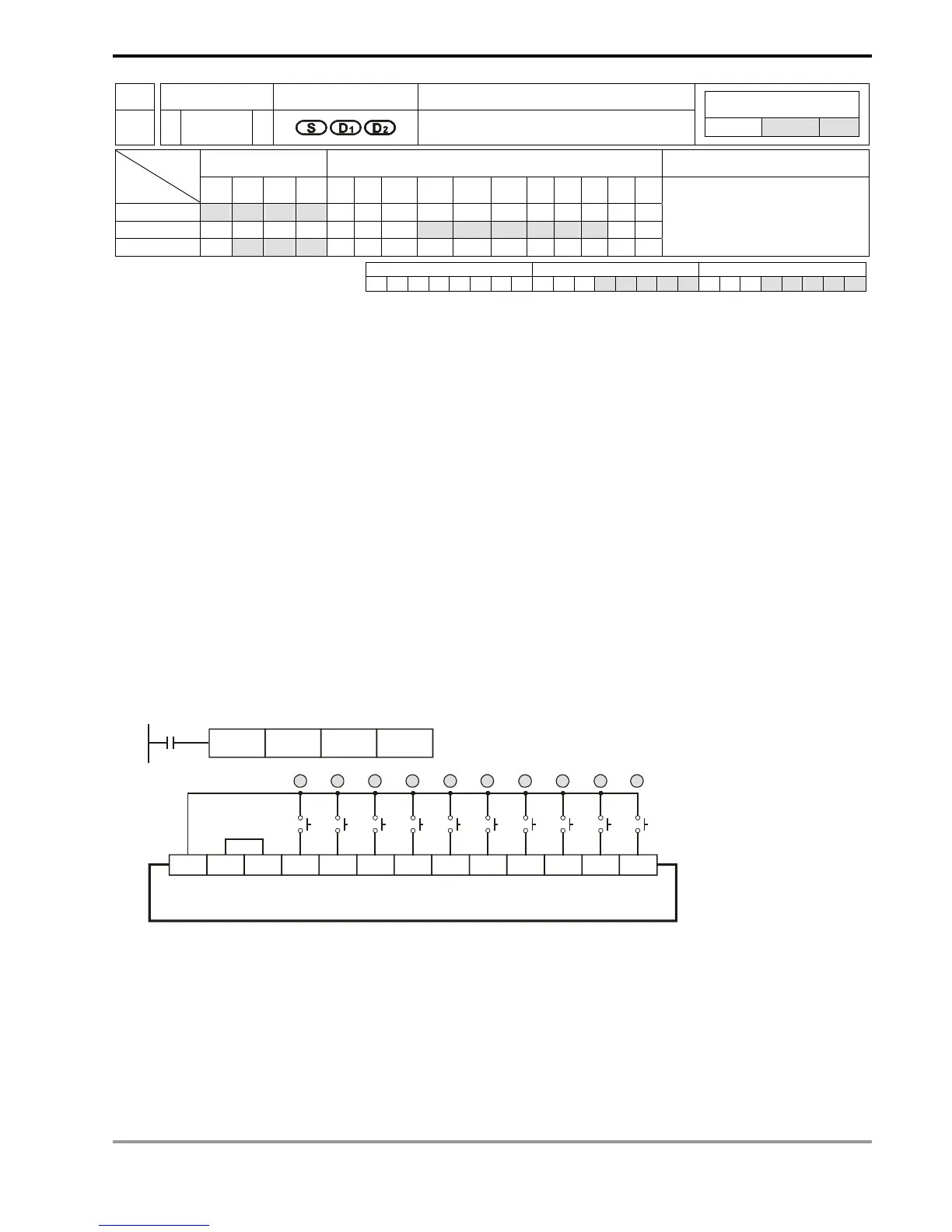
Program Example:
1. Connect the 10 input points starting from X0 to the 10 keys (0 ~ 9). When X20 = On, the instruction will be
executed and the keyed-in values will be stored in D0 in bin form. The key status will be stored in M10 ~ M19.
X20
TKY X0 D0 M10
PLC
0 1 32 4 5 6 7 8 9
X3X2X1X0S/S X6X5X4 X10X7 X11+24V0V