7 Application Instructions API 50-99
DVP-PLC APPLICATION MANUAL
7-48
API Mnemonic Operands Function
63
INCD
Incremental Drum Sequencer
Controllers
ES/EX/SS SA/SX/SC EH/SV
Bit Devices Word Devices Program Steps Type
OP
X Y M S K H KnX KnY KnM KnS T C D E F
S
1
* * * * * * *
S
2
*
D * * *
n * *
INCD: 9 steps
PULSE 16-bit 32-bit
ES EX SS SA SX SC EH SV ES EX SS SA SX SC EH SV ES EX SS SA SX SC EH SV
Operands:
S
1
: Start device in the data table S
2
: No. of counter D: Start No. of the devices for the comparison results
n: Number of data for comparison
Explanations:
1. When S
1
designates KnX, KnY, KnM and KnS, it has to designate K4.
2. In the 16-bit instruction, S
2
has to designate C0 ~ C198 and will occupy 2 consecutive No. of counters.
3. Range of n: 1 ~ 64
4. See the specifications of each model for their range of use.
5. Flag: M1029 (instruciton execution completed)
6. INCD instruction is for the relative control of the multiple output pulses generated by the present value in the
counter.
7. The present value in S
2
is compared with S
1
. S
2
will be reset to 0 whenever a comparison is completed. The
current number of data processed in temporarily stored in S
2
+ 1.
8. When n data have been processed, M1029 will be On for one scan period.
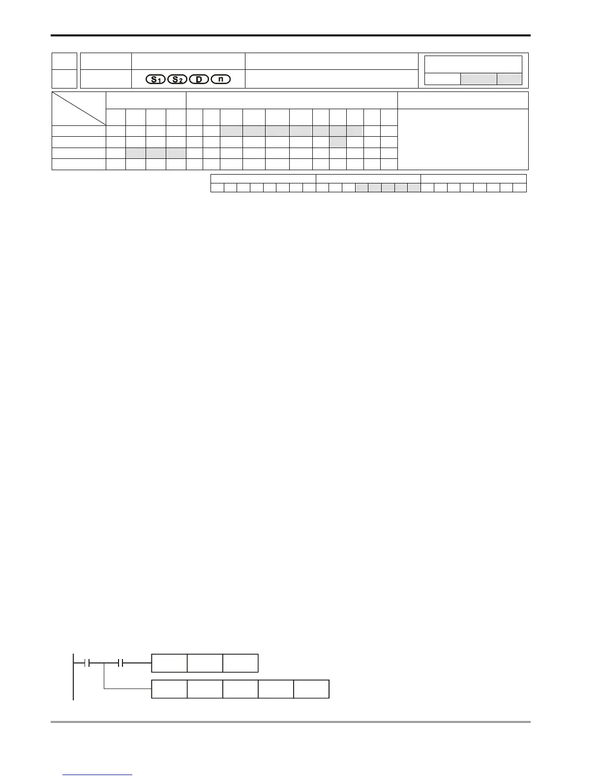
Program Example:
1. Before the execution of INCD instruction, use MOV instruction to write all the set values into D100 ~ D104 in
advance. D100 = 15, D101 = 30, D102 = 10, D103 = 40, D104 = 25.
2. The present value in C10 is compared against the set values in D100 ~ D104. The present value will be reset to
0 whenever a comparison is completed.
3. The current number of data having been processed is temporarily stored in C11.
4. The number of times of reset is temporarily stored in C11.
5. Whenever the content in C11 pluses 1, M10 ~ M14 will also correspondingly change. See the timing diagram
below.
6. After the 5 groups of data have been compared, M1029 will be On for one scan period.
7. When X0 goes from On to Off, C10 and C11 will both be reset to 0 and M10 ~ M14 will all be Off. When X0 is On
again, the instruction will start its execution again from the beginning.
INCD D100 C10 M10 K5
X0
CNT C10 K100
M1013

 Loading...


