7 Application Instructions API 50-99
DVP-PLC APPLICATION MANUAL
7-3
API Mnemonic Operands Function
52
MTR
Input Matrix
Controllers
ES/EX/SS SA/SX/SC EH/SV
Bit Devices Word Devices Program Steps Type
OP
X Y M S K H KnX KnY KnM KnS T C D E F
S
*
D
1
*
D
2
* * *
n * *
MTR: 9 steps
PULSE 16-bit 32-bit
ES EX SS SA SX SC EH SV ES EX SS SA SX SC EH SV ES EX SS SA SX SC EH SV
Operands:
S: Start device of matrix input D
1
: Start device of matrix output D
2
: Corresponding start device for matrix scan
n: Number of arrays in matrix scan
Explanations:
1. S must designate X0, X10…the X points whose 1st digit is “0” and occupies 8 consecutive points.
2. D
1
must designate Y0, Y10…the Y points whose 1st digit is “0” and occupies n consecutive points.
3. D
2
must designate Y0, M0. S0…the Y, M, S points whose 1st digit is “0”.
4. Range of n: 2 ~ 8.
5. See the specifications of each model for their range of use.
6. Flag: M1029 (execution of the instruction is completed).
7. S is the start device No. of all input terminals connected to the matrix. Once S is designated, the 8 points
following the No. will be the input terminals in the matrix.
8. D
1
designate the start device No. of transistor output Y in the matrix scan.
9. This instruction occupies continuous 8 input devices starting from S. n external output terminals starting from
D
1
read the 8 switches of n arrays by matrix scan, obtaining 8 × n multiple-matrix input points. The status of
scanned switches will be stored in the devices starting from D
2.
10. Maximum 8 input switches can be parallelly connected in 8 arrays and obtaining 64 input points (8 × 8 = 64).
11. When the 8-point 8-array matrix inputs are in use, the reading time of each array is approximately 25ms,
totaling the reading of 8 arrays 200ms, i.e. the input signals with On/Off speed of over 200ms are not
applicable in a matrix input.
12. The drive contact of this instruction uses normally On contact M1000.
13. Whenever this instruction finishes a matrix scan, M1029 will be On for one scan period.
14. There is no limitation on the number of times using the instruction, but only one instruction can be executed in
a period of time.
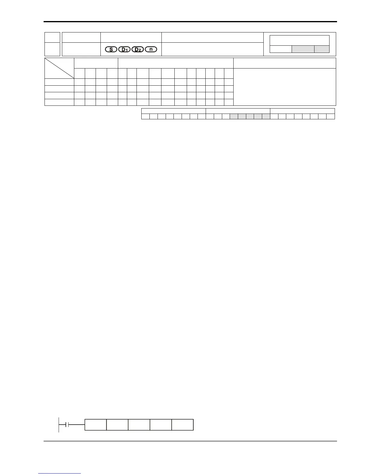
Program Example:
1. When PLC RUN, MRT instruction will start to be executed. The statuses of the external 2 arrays of 16 switches
will be read in order and stored in the internal relays M10 ~ M17, M20 ~ M27.
M1000
MTR X40 Y40 M10 K2

 Loading...


