1 Basic Principles of PLC Ladder Diagram
DVP-PLC Application Manual
1-13
Example Program 1
See the ladder diagram below. There are 2 ways to indicate the ladder by instruction programs with the same result.
Ideal way Less ideal way
LD X0 LD X0
OR X1 OR X1
LD X2 LD X2
OR X3 OR X3
ANB LD X4
LD X4 OR X5
OR X5 ANB
X0 X2 X4
X5X3X1
ANB ANB
The two instruction programs will be converted into the same ladder diagram. The difference between the ideal
one and less ideal one is the operation done by the MPU. For the ideal way, the combination is done block by block
whereas the less idea way combines all the blocks combine with one another in the last step. Though the length of
the program codes of the two ways are equal, the combination done in the last step (by ANB instruction, but ANB
cannot be used continuously for more than 8 times) will have to store up the previous calculation results in advance.
In our case, there are only two blocks combined and the MPU allows such kind of combination. However, once the
number of blocks exceed the range that the MPU allows, problems will occur. Therefore, the best way is to execute
the block combination instruction after a block is made, which will also make the logic sequence planned by the
programmer more in order.
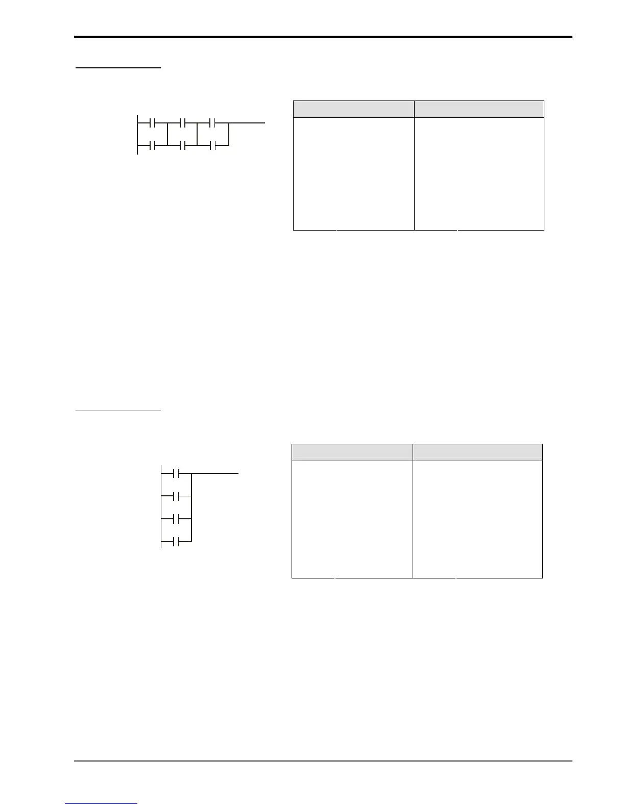
Example Program 2
See the ladder diagram below. There are 2 ways to indicate the ladder by instruction programs with the same result.
Ideal way Less ideal way
LD X0 LD X0
OR X1 LD X1
OR X2 LD X2
OR X3 LD X3
ORB
ORB
X0
X1
X2
X3
ORB
In this example, the program codes and the operation memory in the MPU increase in the less ideal way.
Therefore, it is better that you edit the program following the defined sequence.
Incorrect Ladder Diagram
PLC processes the diagram program from up to down and left to right. Though we can use all kinds of ladder
symbols to combine into various ladder diagrams, when we draw a ladder diagram, we will have to start the diagram
from the left power line and end it at the right power line (In WPLSoft ladder diagram editing area, the right power line
is omitted), from left to right horizontally, one row after another from up to down. See bellows for the frequently seen
incorrect diagrams:

 Loading...


