6 Application Instructions API 00-49
DVP-PLC Application Manual
6-51
API Mnemonic Operands Function
35
SFTL P
Bit Shift Left
Controllers
ES/EX/SS SA/SX/SC EH/SV
Bit Devices Word Devices Program Steps Type
OP
X Y M S K H KnX KnY KnM KnS T C D E F
S * * * *
D * * *
n
1
* *
n
2
* *
SFTL, SFTLP: 9 steps
PULSE 16-bit 32-bit
ES EX SS SA SX SC EH SV ES EX SS SA SX SC EH SV ES EX SS SA SX SC EH SV
Operands:
S: Start No. of the shifted device D: Start No. of the device to be shifted n
1
: Length of data to be shifted
n
2
: Number of bits to be shifted in 1 shift
Explanations:
1. Range of n
1
: 1~ 1,024
2. Range of n
2
: 1 ~ n
1
3. In ES/EX/SS, 1 ≤ n
2
≤ n
1
≤ 512
4. ES/EX/SS series MPU does not support E, F index register modification.
5. See the specifications of each model for their range of use.
6. This instruction shifts the bit device of n
1
bits (desired length for shifted register) starting from D to the left for n
2
bits. S is shifted into D for n
2
bits to supplement empty bits.
7. This instruction adopts pulse execution instructions (SFTLP).
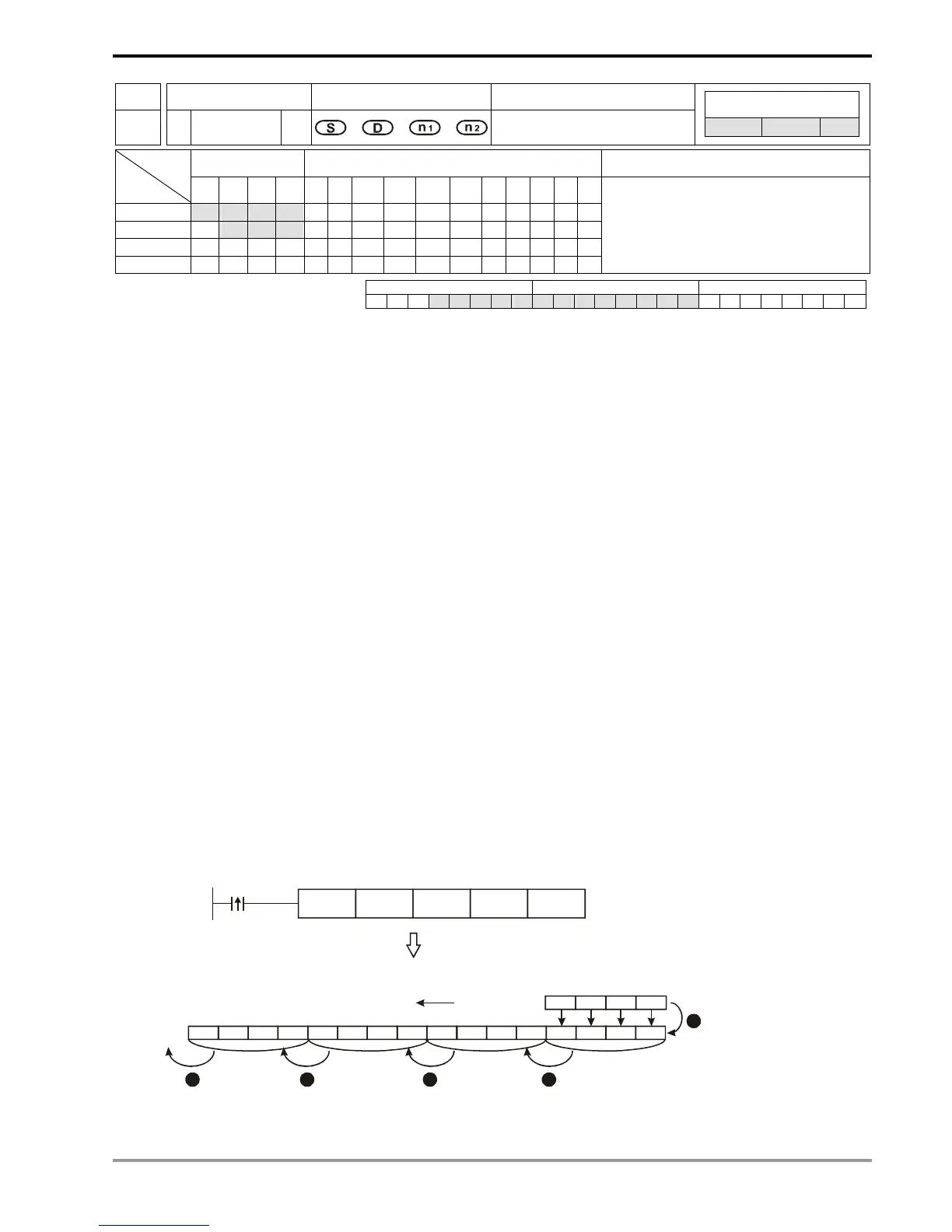
Program Example:
1. When X0 = Off→On, M0 ~M15 will form 16 bits and shifts to the left (4 bits as a group).
2. The figure below illustrates the left shift of the bits in one scan.
n M15 ~ M12 → carry
o M11 ~ M8 → M15 ~ M12
p M7 ~ M4 → M11 ~ M8
q M3 ~ M0 → M7 ~ M4
r X3 ~ X0 → M3 ~ M0 completed
X

 Loading...


