5 Categories and Use of Basic Application Instructions
DVP-PM Operation Instruction
5-6
Length of Operand (16-bit or 32-bit instruction)
The length of operand can be divided into two groups, 16-bit and 32-bit, for processing data of different length.
A prefix ”D” indicates 32-bit instructions.
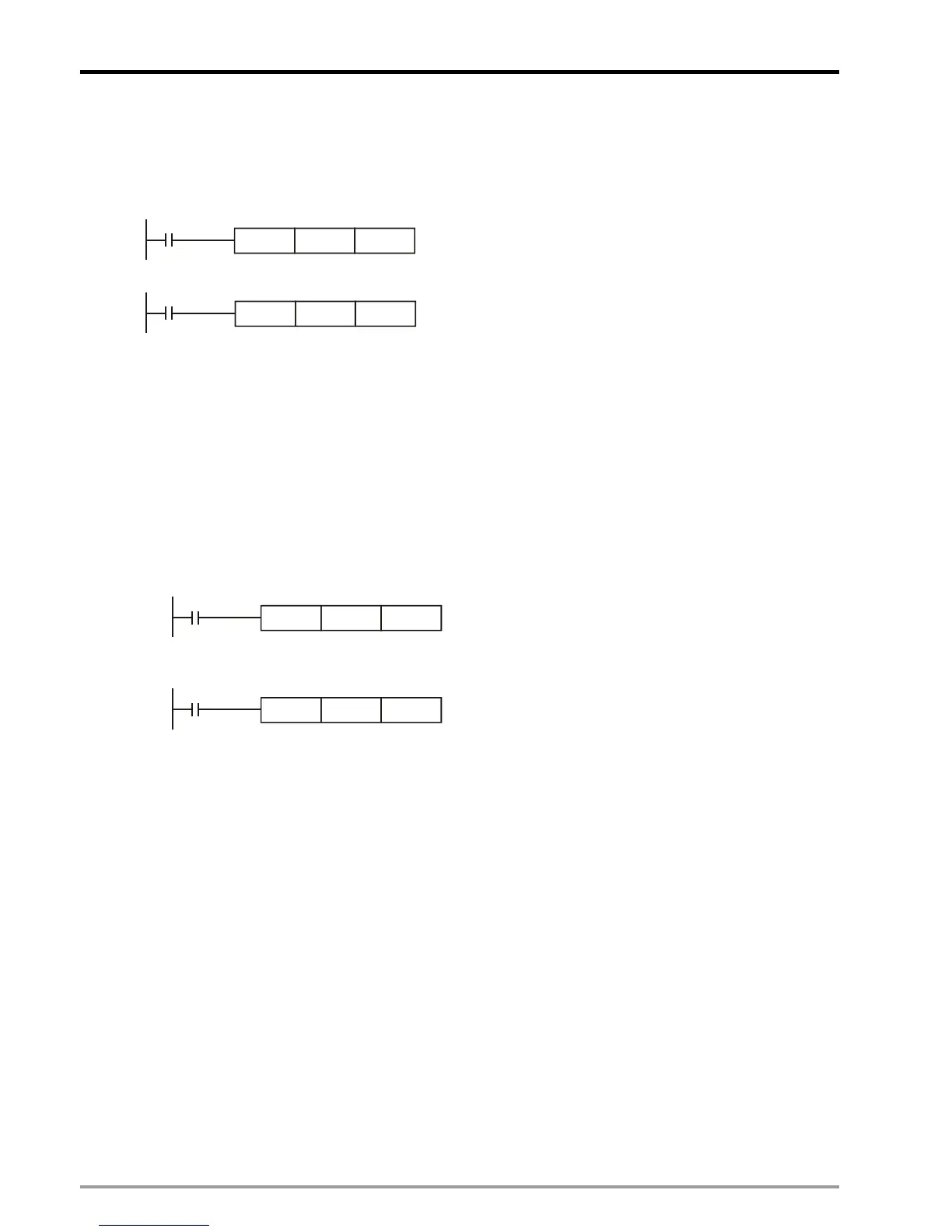
16-bit MOV instruction
X0
K10
D10
MOV
When X0 = ON, K10 will be sent to D10.
32-bit DMOV instruction
X1
D10 D20
DMOV
When X1 = ON, the content in (D11, D10) will be
sent to (D21, D20).
Continuous execution vs. Pulse execution
1. There are two execution types for instructions: continuous execution and pulse execution. Program scan
time is shorter when instructions are not executed. Therefore, using the pulse execution instruction can
reduce the scan time of the program.
2. The ‘pulse’ function allows the associated instruction to be activated on the rising edge of the drive contact.
The instruction is driven ON for the duration of one program scan.
3. In addition, while the control input remains ON, the associate instruction will not be executed for the
second time. To re-execute the instruction the control input must be turned from OFF to ON again.
Pulse execution instruction
X0
D10
D12MOVP
MOVP instruction will be executed once in
present scan period only when X0 goes from
OFF to ON.
Continuous execution instruction
X1
D10
D12MOV
When X1 = ON, MOV instruction will be
re-executed in every scan of program. This is
called continuous execution instruction.
Operands
1. Bit devices X, Y, M, and S can be combined into word device, storing values and data for operations in the
form of KnX, KnY, KnM and KnS in an application instruction.
2. Data register D, timer T, counter C and index register E, F are designated by general operands.
3. A data register D consists of 16 bits, i.e. a 32-bit data register consists of 2 consecutive D registers.
4. If an operand of a 32-bit instruction designates D0, 2 consecutive registers D1 and D0 will be occupied. D1
is the high word and D0 is the low word. This proncipal also applys to timer T, 16-bit counters C0 ~ C199.
5. When the 32-bit counters C200 ~ C255 are used as data registers, they can only be designataed by the
operands of 32-bit instructions.
Operand Data format
1. X, Y, M, and S are defined as bit devices which indicate ON/OFF status.
2. 16-bit (or 32-bit) devices T, C, D, and registers V, Z are defined as word devices.
3. “Kn” can be placed before bit devices X, Y, M and S to make it a word device for performing word-device
operations. (n = 1 refers to 4 bits. For 16-bit instruction, n = K1 ~ K4; for 32-bit instruction, n = K1 ~ K8).
For example, K2M0 refers to 8 bits, M0 ~ M7