2 Hardware Specifications and Wiring
DVP-PM Application Manual
2-6
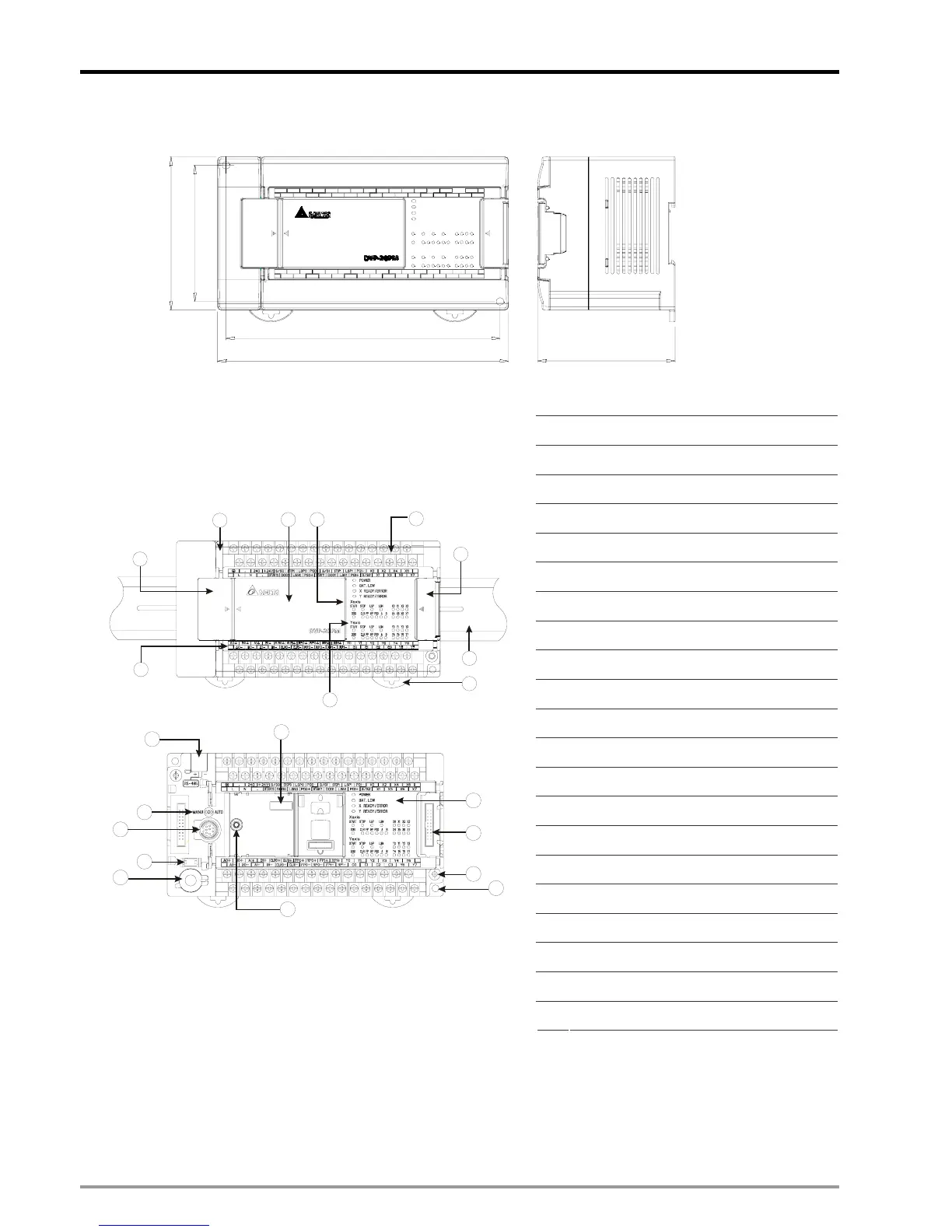
2.1.3 Dimension
174
164
80
82.2
90
(Unit: mm)
Product Profile & Outline:
1 Communication port cover
2 I/O terminal cover
3 Function card cover
4 Input indicator
5 Output indicator
6 I/O terminal No.
7 I/O terminals
8 I/O module connection port cover
9 DIN rail clip
10 DIN rail (35mm)
11 COM2 (RS-485)
12 MANU/AUTO (STOP/RUN) switch
13 COM1 (RS-232)
14 Battery socket
15 Battery
16 Function card port
17 Function card fixing hole
18 POWER/ERROR/BAT.LOW indicators
19 I/O module connection port
20 Case fixing screw
10
2
3
1
7
6
5
9
4
8
20
12
13
11
16
17
15
19
14
18
21
21 Direct mounting hole

 Loading...


