8 Application Examples
DVP-PM Application Manual
8-10
Ladder diagram: Operations:
G0G90X1.759Y87.87
G1Z0.0F19.4
.
.
.
G0X56.164Z5.0
G-Code (NC-Code) which draws trajections
When the program sections 1 ~ 4 are completed, drawing of letters, graphs or any texts by DVP-PM can be
performed by DVP-PM
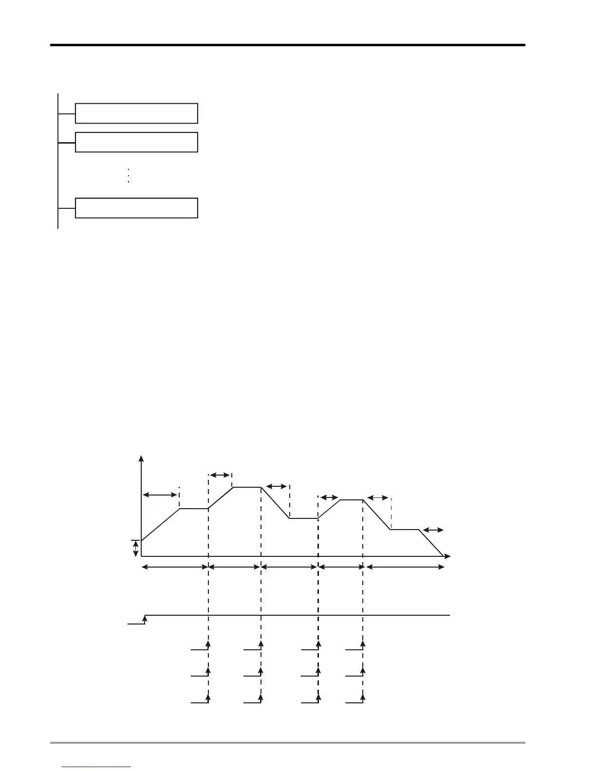
8.3 Planning Variable Speed Operation
This section introduces how to trigger many segments of speed (variable speed) in a fixed route by using
single-speed positioning mode.
8.3.1 Program structure
1. Trigger condition 1: external input signal. X0 ~ X3 switches to the 2
nd
~ 5
th
speed.
2. Trigger condition 2: comparison results of CP. M0 ~ M3 switches to the 2
nd
~ 5
th
speed.
3. Trigger condition 3: Timer. T0 ~ T3 switches to the 2
nd
~ 5
th
speed.
T
ACC
T
DEC
T
ACC
T
ACC
T
DEC
T
DEC
V
BIAS
Start
X0
X1 X2
X3
M0 M1 M2 M3
T0 T1 T2 T3
X7
Frequency (Hz)
Time (ms)
Number of
pulses in
Segment 1
Number of
pulses in
Segment 2
Number of
pulses in
Segment 3
Number of
pulses in
Segment 4
Number of
pulses in
Segment 5
Trigger condition 1
Trigger condition 2
Trigger condition 3
DD1838 (total number of output pulses) = number of pulses in Segment 1 + Segment 2 + … + Segment 5

 Loading...


