2 Hardware Specifications and Wiring
DVP-PM Application Manual
2-8
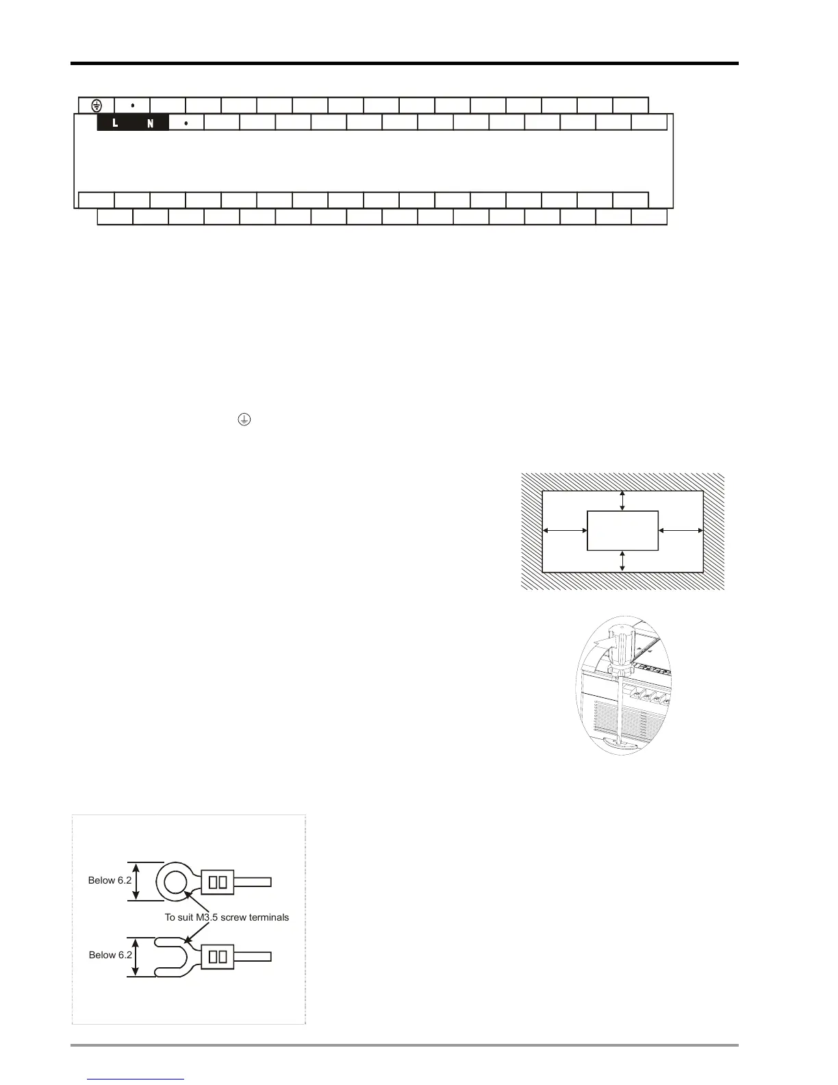
S/S
24G
X1 X3
X5
X7
X10-
X11-
X12- X13- X1 X3 X5 X7
+24V
X0
X2
X4 X6
X10+
X11+ X12+ X13+ X2 X4 X6
C3 Y10- Y11- Y12- Y13- Y14- Y15- Y16- Y17- C3 Y5 Y7
Y10+
Y11+
Y12+ Y13+ Y14+ Y15+ Y16+ Y17+ Y4 Y6Y0 Y1 Y2 Y3
C2C1
C0
DVP-10PM
( AC Power IN, DC Signal IN )
2.2 Installation & Wiring
DVP-PM is an OPEN-TYPE device and therefore should be installed in an enclosure free of airborne dust, humidity,
electric shock and vibration. The enclosure should prevent non-maintenance staff from operating the device (e.g. key
or specific tools are required for opening the enclosure) in case danger and damage on the device may occur.
DO NOT connect AC power input to any of the I/O terminals; otherwise serious damage may occur. Check all the
wiring again before switching on the power. To prevent electromagnetic interferences, make sure the PLC is properly
grounded by ground terminal
.
2.2.1 Mounting and Wiring Notes
Please install DVP-PM in an enclosure with sufficient space around it to
allow heat dissipation, as shown in the figure.
Direct Mounting:
Please use M4 screw according to the dimension of the product.
DVP MPU
> 50mm> 50 mm
> 50mm
> 50mm
DIN-rail Mounting:
DVP-PM can be secured to a cabinet by using the 35mm DIN rail. When
mounting the PLC to 35mm DIN rail, be sure to use the retaining clip to stop
any side-to-side movement of the PLC and reduce the chance of wires
being loose. The retaining clip is at the bottom of the PLC. To secure the
PLC to DIN rail, pull down the clip, place it onto the rail and gently push it up.
To remove the PLC, pull the retaining clip down with a flat screwdriver and
gently remove the PLC from DIN rail.
Wiring notes:
To suit M3.5 screw terminals
Below 6.2
Below 6.2
1. Use O-type or Y-type terminals. See the figure in the left hand side for
its specification. PLC terminal screws should be tightened to 9.50
kg-cm (8.25 in-Ibs). Use 60/75ºC copper conductor only.
2. DO NOT wire empty terminal. DO NOT place the input signal cable
and output power cable in the same wire duct.
3. DO NOT drop tiny metallic conductor into the PLC while screwing and
wiring. Please attach the dustproof sticker to the PLC before the
installation to prevent conductive objects from dropping in. Tear off the
sticker before running the PLC to ensure normal heat dissipation.

 Loading...


