13 CANopen Communication Card
DVP-PM Application Manual
13-13
CRn40: Node control command
[Explanations]
Send out node control commands to the connected nodes. Set value = 1 indicates “Servo On”. Set value = 128
indicates “Servo Off.” Set value = 129 indicates “Error Reset.” For the setting format, please refer to the table
below.
Bit b15~b8] b7~b0]
Content reserved
Servo On: 1
Servo Off: 128
Error Reset: 129
CRn50: SDO access command and status
[Explanations]
Set up the SDO access commands on the node and obtain the status. Please refer to the table below for the
setting format.
Bit b15~b8 b7~b4 b3 b2~b0
Function
Subindex of the the
target OD index.
Data length (unit: byte)
Range: 1~8
Length of data should be specified in
write-in cases
Error flag
Commands:
0: completed
1: write in
(check up )
2: read out
(check up)
3: write in
(No check up)
4: read out
(No check up)
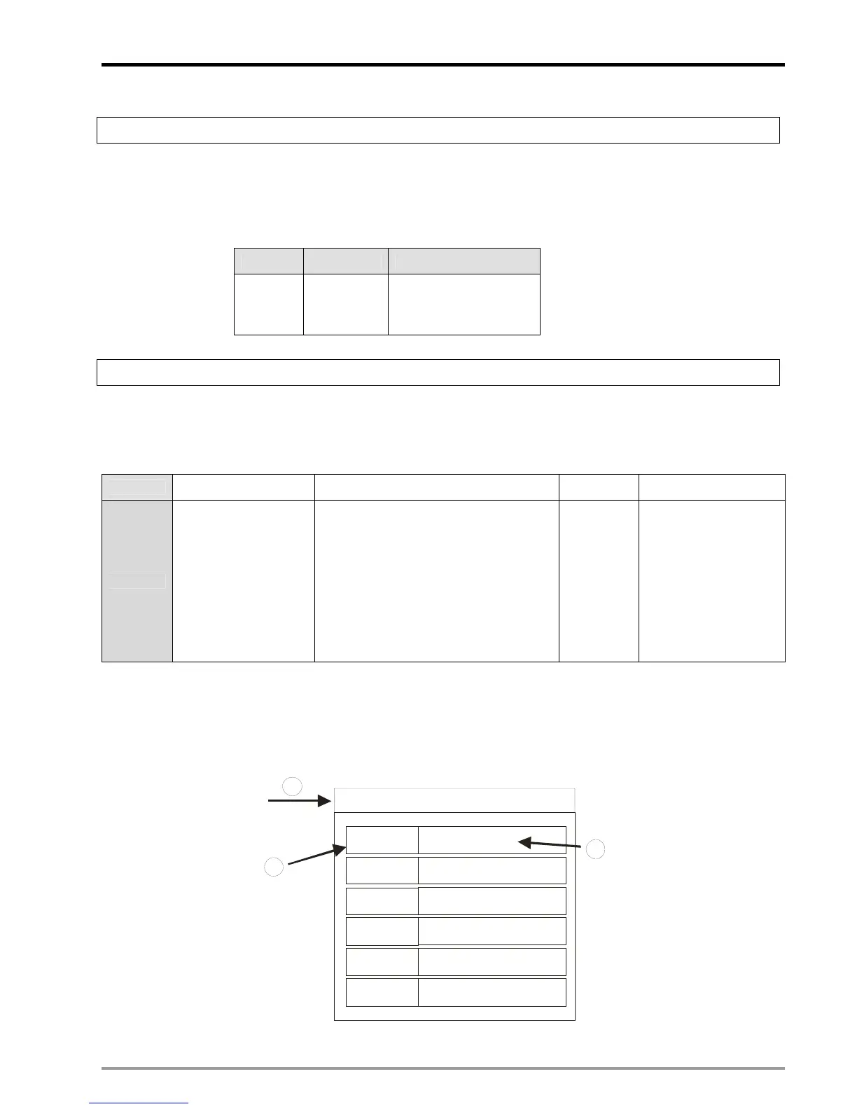
SDO data transmission diagram:
1. Specify the OD index of SDO server in CRn51.
2. Set up the data to be transmitted in CRn52~CRn55.
3. Refer to the above table. Specify the subindex in b15~b8 of CRn50 and the SDO access commands as well.
OD index
Subindex
Data
Data
Data
Data
Data
Data
1
3
2
Subindex
Subindex
Subindex
Subindex
Subindex

 Loading...


