2 Hardware Specifications and Wiring
DVP-PM Application Manual
2-9
2.2.2 Power Input Wiring
The power input type for DVP-PM is AC input. When operating DVP-PM, please note the following points:
1. The range of the input voltage should be 100 ~ 240VAC. The power input should be connected to L and N
terminals. Please note that
wiring AC110V or AC220V to +24V output terminal or digital input points will result in
serious damage on the PLC.
2. The AC power inputs for the MPU and the digital I/O module should be ON or OFF at the same time.
3. Use wires of 1.6mm diameter (or bigger size) for the grounding of PLC.
4. The power shutdown of less than 10ms will not affect the operation of the PLC. However, power shutdown time
that is too long or the drop of power supply voltage will stop the running of the PLC, and all outputs will go “OFF”.
When the power returns to normal status, the PLC will automatically resume operation. (Care should be taken on
the latched auxiliary relays and registers inside the PLC when programming.).
5. The +24V output is rated at 0.5A from MPU. DO NOT connect other external power supplies to this terminal.
Every input terminal requires 5 ~ 7mA to be driven; e.g. the 16-point input will require approximately 100mA.
Therefore, +24V terminal cannot give output to the external load that is more than 400mA.
2.2.3 Safety Wiring
In PLC control system, many devices are controlled at the same time and actions of any device could influence each
other, i.e. breakdown of any device may cause danger or even the breakdown of the entire auto-control system.
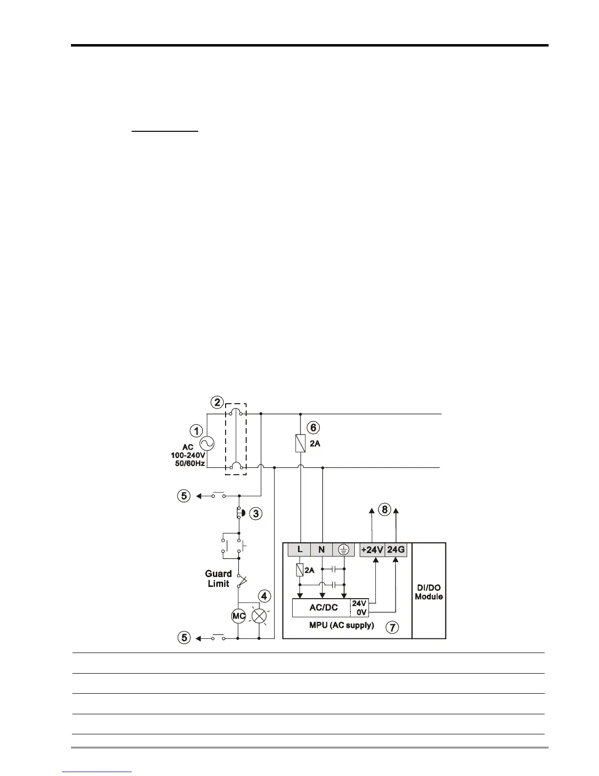
Therefore, we suggest you wire a protection circuit at the power supply input terminal. See the figure below.
c
AC power supply: 100 ~ 240VAC, 50/60Hz
d
Circuit breaker
e
Emergency stop. This button cuts off the system power supply when accidental emergency occurs.
f
Power indicator

 Loading...


