14 High Speed Compare and Capture
DVP-PM Application Manual
14-4
14.2 High Speed Compare Function
High speed Compare applies FROM/TO instructions for accessing the comparison method and comparison data.
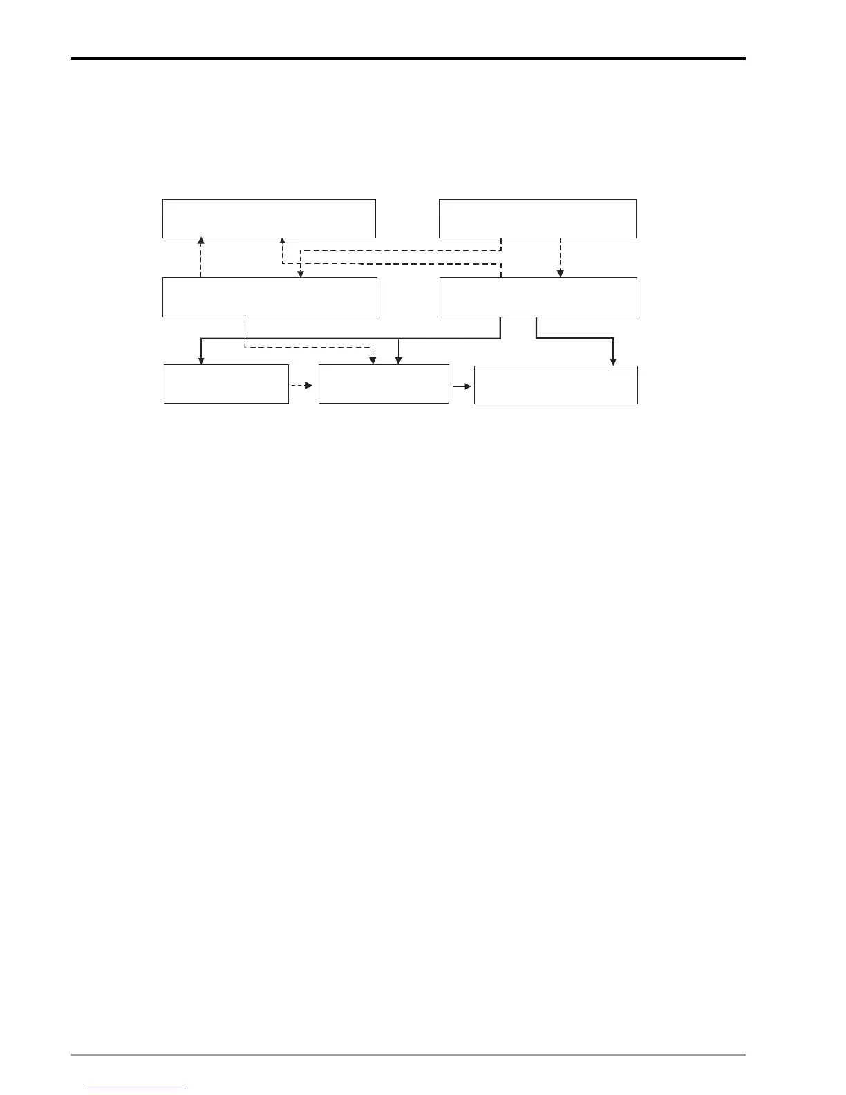
The comparison function is illustrated as the below diagram.
(B)FROM K253 K1 D0 D50 (A)TO K253 K1 D0 D50
(D)Data register DRn(n=0~7) (C)Control register CRn(n=0~7)
(E)Data source
for com pari so n
(F)Compare method
(G)Select output
terminal and counters
※Dashed lines indicate data access process and solid lines indicate the control setting process
Block A: Use TO instruction to write data into control registers (Block C) and data registers (Block D)
Block B: Use FROM instruction to read data from control registers (Block C) and data registers (Block D)
Block C: According to the data specified by TO instruction, control registers set up the data source (Block E),
Compare method (Block F) and output terminal setting (Block G).
Block D: Data registers store the data specified by TO instruction and Compare the data with the data source
in Block E.
Block E: There are 5 sets of data source including current position of X/Y/Z axis, count value of C200 (current
position of Master / MPG of X-aixs) and count value of C204 (MPG of Y-axis). For settings of high
speed counters C200 and C204, please refer to Ch3 of this manual.
Block F: Compare method: compare the data in Block D and Block E by 3 conditions: ≧, ≦, and =. When
one of the conditions is met and the trigger method is set as “Set” (Bit7-6=0), the output terminals
(CLR0, CLR1, Y2, Y3) and counters C200/C204 (when RST signal is triggered, count value will be
cleared and cannot resume counting) will be set ON. When trigger method is set as “Rst” (Bit7-6=1),
the output terminals and counters C200/C204 (ON state will be reset and can resume counting) will
be reset.
Note: In this case, the LEDs will not respond when CLR0, CLR1, Y2 or Y3 is ON. To identify their
status, connect CLR0-, CLR1-,C2 with 24G; CLR0+, CLR1+, Y2 and Y3 with Xn, and S/S2 with +24V.
By this wiring method the LED of the corresponding X point will be ON when one of the terminals are
ON.
Block G: When the conditions of comparison are met, one of the 6 output settings including CLR0, CLR1, Y2
(00M), Y3 (00M), C200 and C204 will be set ON or reset.
Process of comparison:
Set up compare settings and comparison data (Block A) → Comare specified data (Block D) with data source
(Block E) by the conditions set in Block F → Set/Rst output terminals or counters C200/C204 according to
settings in Block G.

 Loading...


