8 Application Examples
DVP-PM Application Manual
8-11
8.3.2 Design Example Program
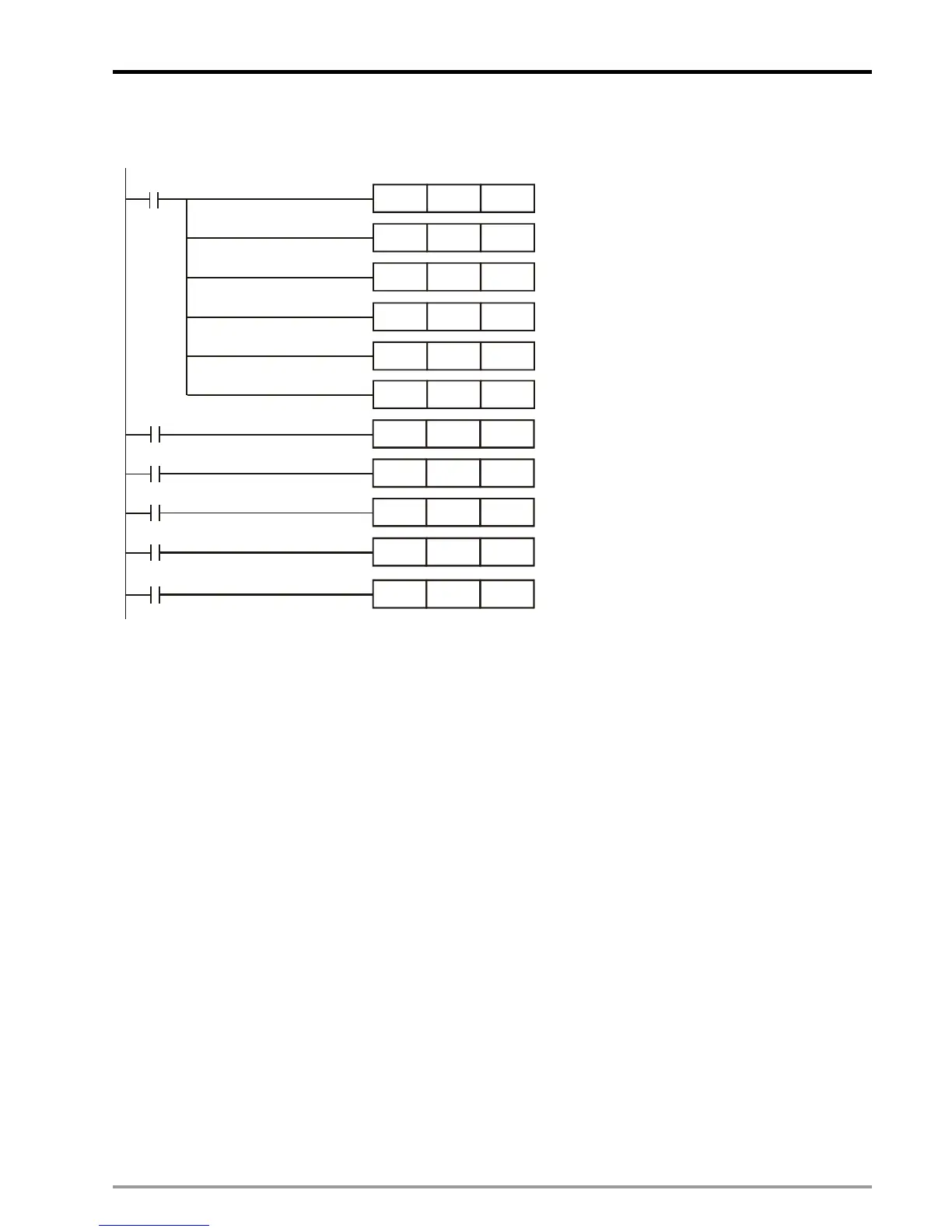
Ladder diagram of trigger condition 1: Operations:
Set up bias speed of X axis (V
BIAS
)
Set up acceleration time of X axis (T
ACC
)
Set up deceleration time of X axis (T
DEC
)
Clear the current position of X axis as 0
Set up the total distance of all segments for
X axis
Set up the operation speed for the 1
st
segment on X axis
X0 = ON, modify the operation speed into
20,000Hz
X1 = ON, modify the operation speed into
9,000Hz
X2 = ON, modify the operation speed into
18,000Hz
X3 = ON, modify the operation speed into
7,000Hz. Pulse output will be finished in this
segment.
X0
D1824
D1836
D1837
DMOV
D1848
DMOV
D1838
DMOVP
D1840
M1002
K0
K100000
K10000
K20000
DMOV
MOV
MOV
MOV
K100
K100
K100
D1840
D1840
X1
K9000
K18000
K7000
D1840
D1840
X2
X3
H102
D1846
X7
DMOVP
DMOVP
DMOVP
DMOVP
X7 = ON, enable single speed postioning
mode of X axis.

 Loading...


