3 Functions of Devices in DVP-PM
DVP-PM Application Manual
3-1
3.1 Devices in DVP-PM
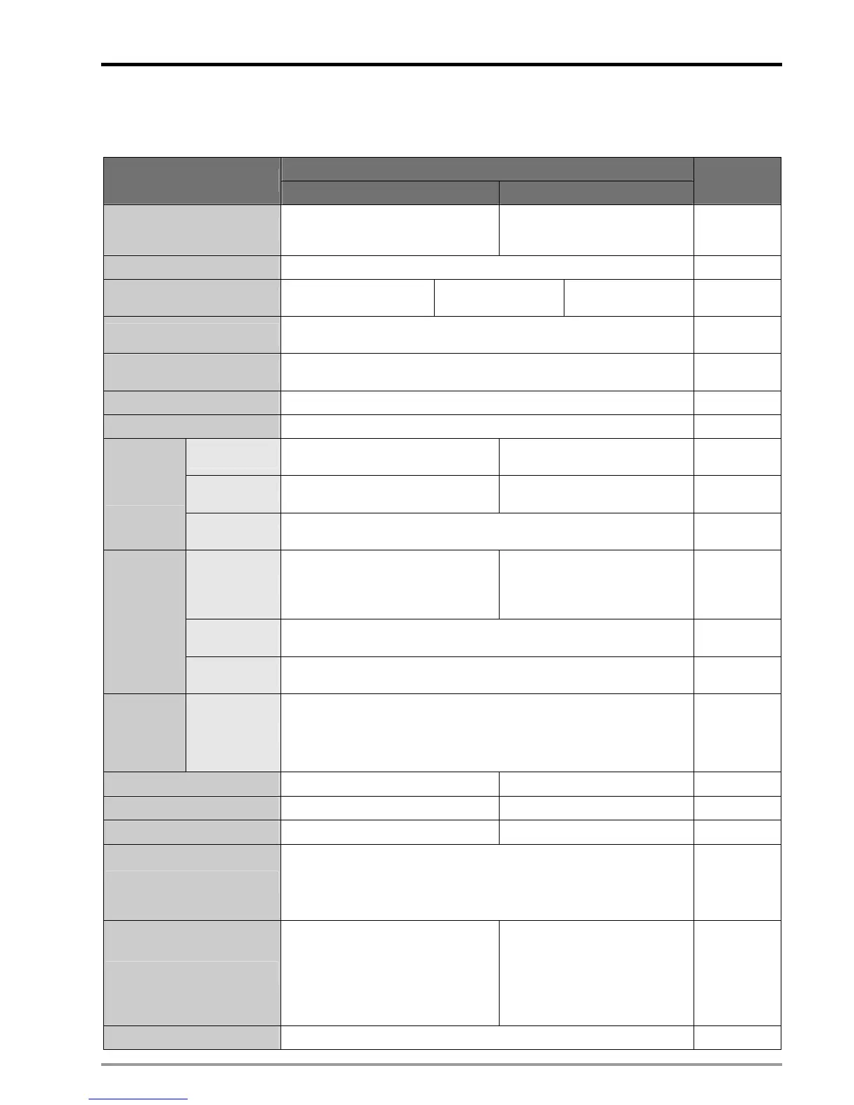
Function Specifications:
Specifications
20PM 10PM
Note
Control system
2-axis synchronous linear/arc
interpolation and independent 2-axis
control (*5)
4-axis synchronous interpolation
and 4-axis independent control
Program storage Built-in 64k steps storage device
Control units Motor system (pulse)
Combined
system(pulse/length)
Machine system
(length)
Access method for I/O module
Access CR (Control register) of the I/O module by FROM/TO instructions.
System uses 2 CRs for 32-bit data.
Serial connection with MPU
When used as an I/O module, MPU accesses the built-in CR0 ~ CR199 (maps
to D1500 ~ D1699) of DVP-PM
Pulse output system Differential output in 3 modes: Pulse/Dir, FP(CW) / RP(CCW), A/B phase
Maximum speed For single axis: 500K PPS. For interpolation axis: 500K PPS
Operation switch
AUTO/MANU (auto/manual switch),
START, STOP
STOP/RUN (auto/manual switch)
Detector
DOG, LSP (positive limit), LSN (negative
limit), PG0 (zero point)
X0, X2, X4, X6 (DOG signal)
X1, X3, X5, X7 (Zero point signal)
Input signal
General input
point
X0 ~ X7, expandable up to 256 points (MPU + I/O module)
Servo output
FP (forward pulse), RP (reverse pulse),
CLR (clear signal)
Y10+, Y10-, Y12+, Y12-, Y14+,
Y14-, Y16+, Y16- (forward pulse)
Y11+, Y11-, Y13+, Y13-, Y15+,
Y15-, Y17+, Y17- (reverse pulse)
General output
point
Y0 ~ Y7, expandable up to 256 points (MPU + I/O module)
Output signal
COM port
COM1: RS-232 (Slave only); COM2: RS-485 (can be Master or Slave)
COM3: Optional RS-232 / RS-485 communication card (Slave only)
Special I/O
module
Optional
Shares all right-side modules with DVP-EH2 including AD, DA, PT, TC, XA,
PU, etc (maximum 8 modules expandable).
The left side of MPU can connect to high-speed I/O modules (maximum 8
modules extendable).
Extended
modules will
not occupy
any digital I/O
points.
Basic instruction 27 27
Application instruction 130 130
Motion instruction 22
M -Code
z M02: End of OX0 ~ 99 motion subroutine
z M00 ~ M01, M03 ~ M101, M103 ~ M65535: used as pause of the program,
can be applied acccroding to actual needs.
z M102: End of O100 main program
G-Code
G0 (hi-speed positioning), G1 (linear
interpolation), G2 (clockwise arc
interpolation), G3 (counter-clockwise arc
interpolation), G4 (pause), G17(X-Y
plane), G18(X-Z plane), G19(YZ plane),
G90 (absolute positioning), G91 (relative
positioning)
N/A
Self-diagnosis Displaying errors such as parameter error, program error and external errors

 Loading...


