13 CANopen Communication Card
DVP-PM Application Manual
13-27
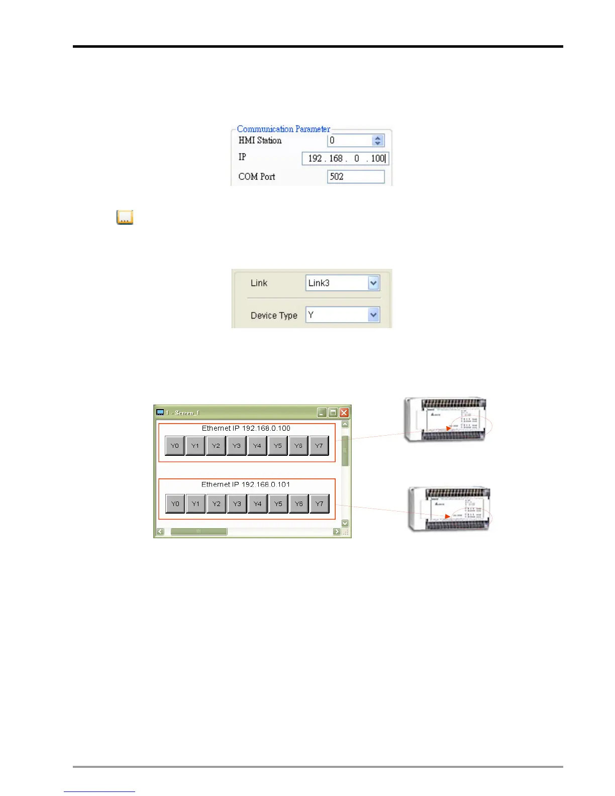
5. Set up the IP of the created device. Click the created device and enter its IP in “Communication
Parameter” column to configure the IP address of one DVP-FPMC. The setting procedure of the other
DVP-FPMC is the same. Create Link4 and specify its IP as well.
6. After the devices are created, create an object in the editing area. Click the object and click the icon
in the Property column to open the input window of Write Address / Read Address. Select the
created device (Link3) in “Link”. In this way, the object can be operated to control the devices of Slave
through Ethernet.
Design the buttons Y0~Y7 for both DVP-PM according to the above procedure as the disgram below.
Buttons Y0~Y7
correspond to Y0~Y7 of Link3 (Slave1) and Link4 (Slave2). When the above settings
are completed, the Ethernet connection between HMI and the 2 DVP-PM can be performed.
IP: 192.168.0.100
IP: 192.168.0.10
13.7.2 Communication between DVP-FPMC and PMSoft
PMSoft is featured with Ethernet function through DVP-FPMC. The ethernet communication interface
between DVP-PM and PC supports software functions including program download/upload and
monitoring on PMSoft.
Hardware Settings
For external wirings, the user only needs to connect the Ethernet COM ports on DVP-FPMC and PC
through an Ethernet cable. When connecting with PC, the Ethernet indicator on DVP-FPMC will be ON in
nomal connection status. If the indicator is OFF, please check the hardware configuration or PC settings.

 Loading...


