3 Functions of Devices in DVP-PM
DVP-PM Application Manual
3-16
3.8 Numbering and Functions of Registers [D]
3.8.1 Data Register [D]
16-bit data register stores the value between -32,768 ~ +32,767. The MSB (Most Significant Bit) is also the sign bit
indicating the value as positive “+” or negative “-“. Two 16-bit registers can be combined into a 32-bit register (D+1, D;
register with smaller number is low word) storing the value between -2,147,483,648 ~ +2,147,483,647. Also, MSB is
the sign bit.
General purpose
D0 ~ D199, 200 points, can be modified into latched area by setting up
parameters.
Latched
D200 ~ D999, D3000 ~ D9999, 7,800 points, can be modified into
non-latched area by setting up parameters.
Special purpose D1000 ~ D2999, 2,000 points, some are latched
Data register
D
Index register V, Z V0 ~ V7, Z0 ~ Z7, 16 points
Total 10,000
points
File register K0 ~ K9,999, MPU 10,000 points, fixed as latched 10,000 points
There are 4 types of registers:
1. General purpose register: When DVP-PM goes from AUTO to MANU
(STOP->RUN) or the power is switched
off, the data in the register will be cleared to “0”. When M1033 = ON and DVP-PM goes from AUTO to MANU
(STOP->RUN), the data will not be cleared but will still be cleared to “0” when the power is OFF.
2. Latched register: When the power of DVP-PM is switched off, the data in the register will not be cleared and
will retain the value before the power is OFF. You can use RST or ZRST instruction to clear the data in the
latched register.
3. Special purpose register: Every register of this kind has its special definition and purpose, mainly for storing
the system status, error messages and monitoring status. See 3.10 and 3.11 for more details.
4. Index register V, Z: V is a 16-bit register, and Z is a 32-bit register. V0 ~ V7, Z0 ~ Z7, total 16 points.
3.8.2 Index Registers [V], [Z]
V0
Z0
16 bit
32 bits
Register V is a 16-bit register and can be written and read as a
general data register. V as a general register can only be used in
16-bit instructions.
Z is a 32-bit register. Z as a general data register can only be used
in 32-bit instructions.
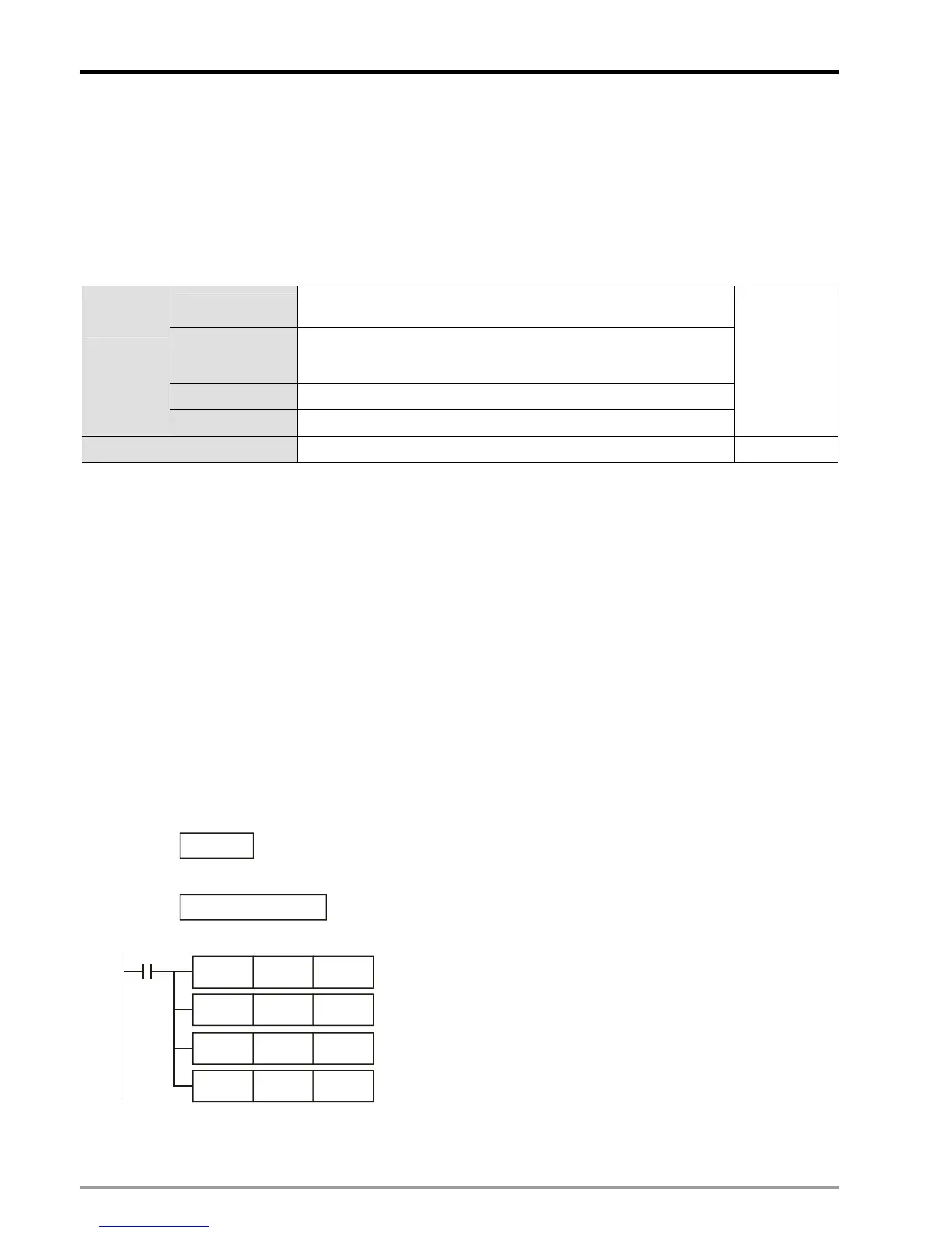
K14 Z1
X0
K8 V0
MOV
DMOV
D3@Z1 D4@V0
D0@V0 D2@Z1MOV
DMOV
When X0 = ON, V0 = 8, Z1 = 14.
D0@V0 = D8, D2@Z1 = D16
The content in D8 will be moved to D16
The content in D17 will be moved to D12
V and Z for modifying the operands can be used in both 16-bit and
32-bit instructions (as the example).
The index register can be used as normal operands for moving or comparison on word devices (KnX, KnY, KnM, KnS,
T, C, D) and bit devices (X, Y, M, S).