2 Hardware Specifications and Wiring
DVP-PM Application Manual
2-7
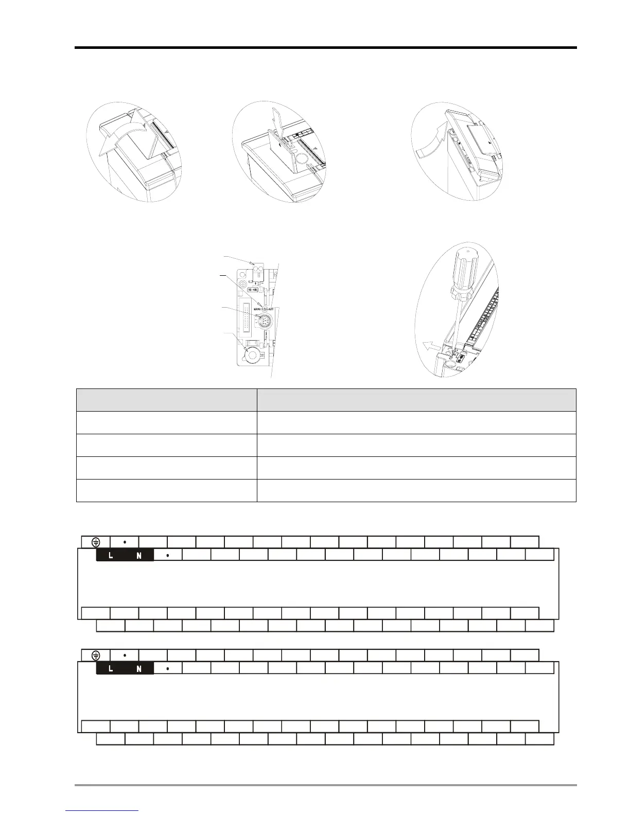
COM1 cover Left-side port cover
Ports under left-side port cover Screw driver is required for removing RS-485 terminal
Battery
COM 1 (RS-232)
MANU / AUTO switch
COM 2 (RS-485)
Removable Terminal Block
Part Description
COM2 (RS-485) For both master and slave modes
MANU/AUTO (STOP/RUN) switch RUN/STOP control
COM1 (RS-232) Slave mode (can be used with COM2 at the same time)
Battery The battery shall be changed within 1 minute
Wiring Terminals: See 2.1.2 for detailed electrical specifications
START0
24G
DOG0 LSN0 PG0+ START1 DOG1 LSN1 PG1+ S/S2 X1 X3 X5 X7
+24V S/S0 STOP0 LSP0 PG0- S/S1 STOP1 LSP1 PG1- X0 X2 X4 X6
B1- CLR0- CLR1- FP0- RP0-
FP1-
RP1- C0 C1 C2 C3 Y5 Y7
CLR0+ CLR1+ FP0+ RP0+ FP1+ RP1+ Y0 Y1 Y2 Y3 Y4 Y6A0+ B0+ A1+ B1+
A1-B0-
A0-
DVP-20PM00D
( AC Power IN, DC Signal IN )
START0
24G
DOG0 LSN0 PG0+ START1 DOG1 LSN1 PG1+ S/S2 X1 X3 X5 X7
+24V S/S0 STOP0 LSP0 PG0- S/S1 STOP1 LSP1 PG1- X0 X2 X4 X6
B1- CLR0- CLR1- FP0- RP0- FP1- RP1- FP2- RP2- C2 C3 Y5 Y7
CLR0+ CLR1+ FP0+ RP0+ FP1+ RP1+ FP2+ RP2+ Y2
Y3
Y4 Y6A0+ B0+ A1+ B1+
A1-B0-
A0-
DVP-20PM00M
( AC Power IN, DC Signal IN )

 Loading...


