11 G-code Application
DVP-PM Application Manual
11-16
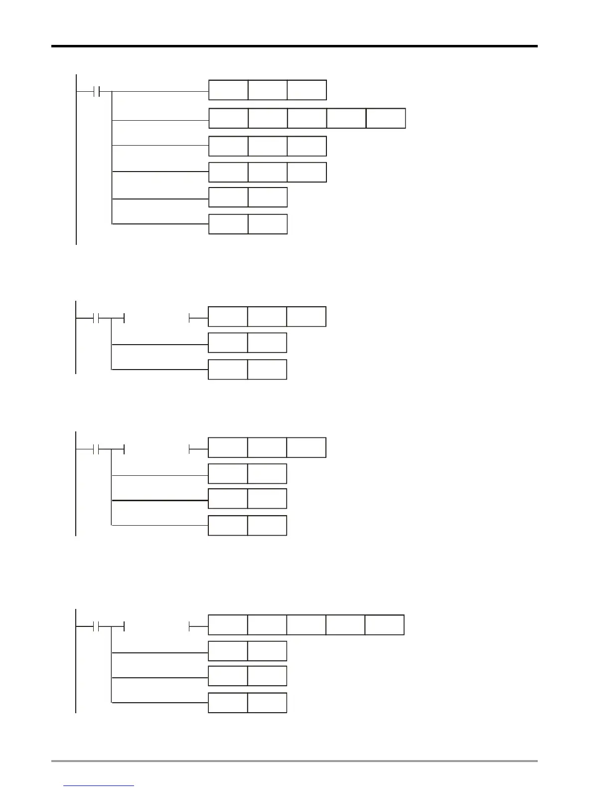
M0
TO
K255 K0
MOV
K50 D3000
MOV
K10
D3001
Specify Group with 10 groups
Initialize the file
conversion process
Specify length of recipe
with 50 words
K0 K1
MOV
K1 D66
SET
M24
RST
M0
Step 2: HMI reads the value in D65 as the command to control the recipe. D65 = 1 indicates changing the
recipe group number.
M24
MOV
K1 D65
SET
M25
RST
M24
LD= D65 K0
Step 3: When recipe group number is changed, the value in D65 becomes 0. After this, write in the recipe
command to download next group and increase the recipe group number in D66.
M25
MOV
K4
D65
SET
M26
RST
M25
LD=
D65 K0
INCP
D66
Step 4: The value in D65 will be cleared as 0 every time when modified. When one group of recipe is
received, conduct file conversion to convert the received data into ASCII codes and store the converted data
inD3002~D3502. When the above process is completed, repeat the step to download the next group.
M26
TO
K255
K2
RST
M26
SET
M24
LD=
D65 K0
SET
M27
D3000 K1
Step 5: If errors occur in file conversion, D3000 will store the error code 0xffff. Users can stop the next
 Loading...


