13 CANopen Communication Card
DVP-PM Application Manual
13-23
Normal mode
In normal mode, the user has to set up PDO parameters between DVP-FPMC (Master) and the Slave. In
addition, use FROM/TO instructions to set up the control registers of DVP-FPMC and apply SDO protocol to
write in the PDO parameters of servo. Please follow the PDO setting process below:
z PDO transmission parameter settings
PDO parameters contain Frame ID and synchronization cycle. Set range of frame ID is between
181h~578h. Please note that Frame ID and synchronization cycle should be the same between the
corresponding PDOs of Master and Slave. The 2 types of PDO, the transmitting PDO (TPDO) and the
receiving PDO (RPDO) will be explained as below:
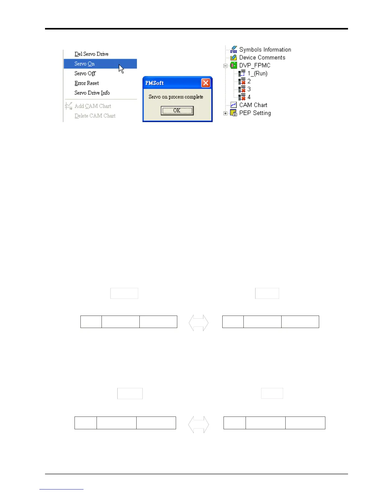
1. TPDO settings
1800H~183FH of DVP-FPMC serves as TPDO, corresponding to RPDO of the Slave. For example, set
up the OD index H1800 (TPDO) of Master to communicate with the OD index 143F(RPDO) of Slave
with the frame ID H181 and sync cycle time 240 as the diagram below.
Transmit PDO
FPMC
Received PDO
H1800
CR#
Frame ID=H181
Sync cycle=240
OD
Index
143F
Slave
Frame ID=H181
Sync cycle=240
2. RPDO settings
1400H~143FH of DVP-FPMC serves as RPDO, corresponding to TPDO of the Slave. For example, set
up the OD index H1438 (RPDO) of Master to communicate with the OD index 1800 (TPDO) of Slave
with the frame ID H400 and sync cycle time 5 as the diagram below.
Received PDO
FPMC
Transmit PDO
Frame ID=H400
Sync Cycle=5
H1438
CR# OD Index
1800
Slave
Frame ID=H400
Sync Cycle=5
z PDO mapping parameter settings
Set up the mapping target and the data length of PDO data buffer. The max data length can be 64 bits,

 Loading...


