3 Functions of Devices in DVP-PM
DVP-PM Application Manual
3-10
Functions of counters:
The counters count once when CNT instruction is driven once. When CNT instruction is executed and the PV reaches
SV, the associated output coil will be ON. SV can be K value (decimal) or D register
16-bit counters C0 ~ C199:
1. The set range of 16-bit counter: K0 ~ K32,767. SV=K0 is the same as SV=K1, i.e. the associated output contact
will be ON immediately when counter is activated.
2. PV in the general purpose counter will be cleared when the power of DVP-PM is OFF. If the counter is a latched
(accumulative) type, PV and the contact status will be retained, and PLC will resume counting after the power is
ON again.
3. If you use MOV instruction or PMSoft to send a value bigger than SV to the present value register of C0, when
X1 goes from OFF to ON, the associated contact of counter C0 will be ON and its PV will equal SV.
4. SV can be K value (decimal) or D register (Special data register D1000~D2999 is not included).
5. Constant K should be a positive value for SV, however, values in data register D can be positive or negative.
When PV reaches up to 32,767, the next PV will turn to -32,768.
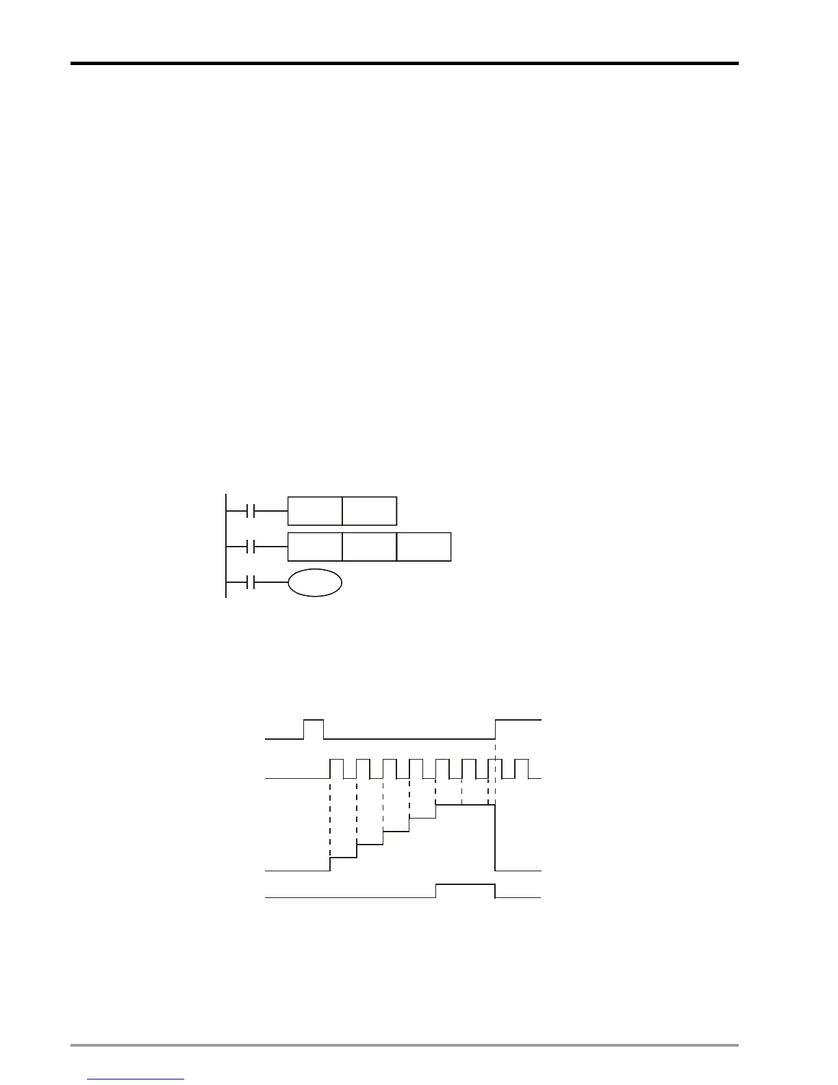
Example:
LD X0
RST C0
LD X1
CNT C0 K5
LD C0
OUT Y0
C0
Y0
X1
C0 K5CNT
X0
C0RST
1. When X0 = ON, RST instruction is executed, PV in C0 will be cleared and the associated contact will be reset.
2. When X1 goes from OFF to ON, PV in the counter will count up (plus 1).
3. When the counting of C0 reaches SV = K5, the contact of C0 will be ON. X1 input signal comes afterwards will
not be accepted by C0, ad PV of C0 will stay at K5.
X0
X1
Contacts Y0,C0
PV in C0
0
1
2
3
4
5
0
SV
32-bit general count-up/count-down counters: C208 ~ C255(20PM) / C220~C255(10PM)
1. The setup range of 32-bit counter: K-2,147,483,648 ~ K2,147,483,647. Counting mode (count-up/count-down) of
the counter is designated by ON/OFF status of special auxiliary relay M1208 ~ M1255. For example, when
M1255 = OFF, C255 will be a count-up counter; when M1255 = ON, C255 will be a count-down counter.
2. SV can be K value (decimal) or D register (Special data register D1000~D2999 is not included). If a D register is

 Loading...


