a. Captioned screens
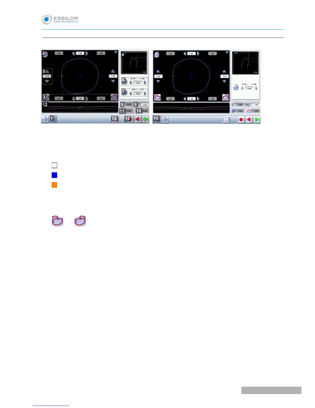
1. High-base bevel screen “front surface monitoring”
2. Work area
Image of the shape to be edged:
Frame shape at bottom of groove
Bevel trajectory on rear surface
Bevel trajectory on rear surface if the lens used is too thin to achieve the desired finish.
3. Cursor movement
The cursor is represented by the square located along the shape. To move it, select it directly or use the
and buttons.
4. Zoom window
Represents the bevel profile at the position of the cursor.
5. Shelf bevel value (8 or 4 values)
◦ Nasal (the value must be between 0.25 and 3 mm)
◦ Mid-nasal (the value must be between 0.25 and 3 mm)
◦ Upper (the value must be between 0.25 and 3 mm)
◦ Mid-upper (the value must be between 0.25 with 3 mm)
◦ Temporal (the value must be between 0.25 and 3 mm)
◦ Mid-temporal (the value must be between 0.25 and 3 mm)
◦ Lower (the value must be between 0.25 and 3 mm)
◦ Mid-lower (the value must be between 0.25 and 3 mm)
6. Width of the flat side of the bevel
The value of the flat side of the bevel must be between 0.1 mm and 1 mm.
7. Front surface tracking value
The value of front surface tracking must be between 0 mm and 1.3 mm. This value is definable only in
the “front surface tracking” screen.
 Loading...