190-02246-10 GI 275 Part 23 AML STC Installation Manual
Rev. 11 Page 4-35
4.5.1 Configuration Module Installation
GI 275 connector assemblies serve as housing for configuration modules. This section lists configuration
module assemblies and installation procedures for installations.
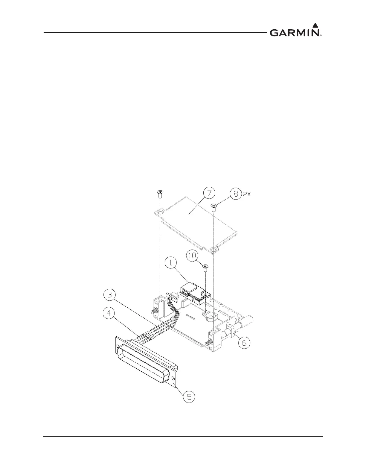
Refer to Figure 4-25 for details and item numbers referenced in the following procedure.
1. Strip back approximately 0.17 inches of insulation from each wire of the 4-conductor wire harness
(3). It is the installer’s responsibility to determine the proper length of insulation to be removed.
2. Crimp a pin (4) to each conductor.
3. Ensure that the wire is visible in the inspection hole, and that the insulation is 1/64 to 1/32 inches
from the end of the contact.
4. Insert newly crimped pins and wires (3, 4) into the connector housing (5) location. For details,
refer to the applicable interconnect drawings.
5. Attach the module (1) to the backshell (6) using a pan head screw (10).
6. Plug the 4-conductor wire harness (3) into the connector on the module (1).
7. Orient the connector housing (5) so that the 4-conductor wire harness (3) is on the same side of the
backshell (6) as the module (1).
8. Attach the cover (7) to the backshell (6) using two screws (8).
Figure 4-25 Jackscrew Backshell Assembly
(Potted Configuration Module)

 Loading...


