190-02246-10 GI 275 Part 23 AML STC Installation Manual
Rev. 11 Page 3-15
3.2.6 HSDB Architecture
The HSDB architecture allows for many connection possibilities. The Ethernet architecture limitations/
options shown in this section are used as a guide for common LRU combinations. Block diagrams are
illustrated in Figure 3-2 through Figure 3-8. A summary of Garmin LRUs with HSDB capability and
available ports is shown in Table 3-17.
Table 3-17 Garmin LRU HSDB Port Summary
The following steps/figures are used as a guide in making HSDB connections (not all possibilities are
included):
1. The Primary ADI and the display with the second ADAHRS or standby (if applicable) must be
directly connected.
2. When multiple GI 275 indicators are installed, they must be connected to each other directly in
series.
3. The GTN 6XX/7XX, GTN Xi, GPS 175, GNX 375, or GNC 355, if installed, must be connected
directly to a GI 275 or a GMC 605 (GFC 600) that is directly connected to a GI 275.
4. LRUs not installed under this STC must still meet the installation requirements that are applicable
to those LRUs.
5. Choose the figure that most closely represents the aircraft’s equipment and cross out any LRUs not
installed. Apply the rules above to complete the HSDB connections, if necessary.
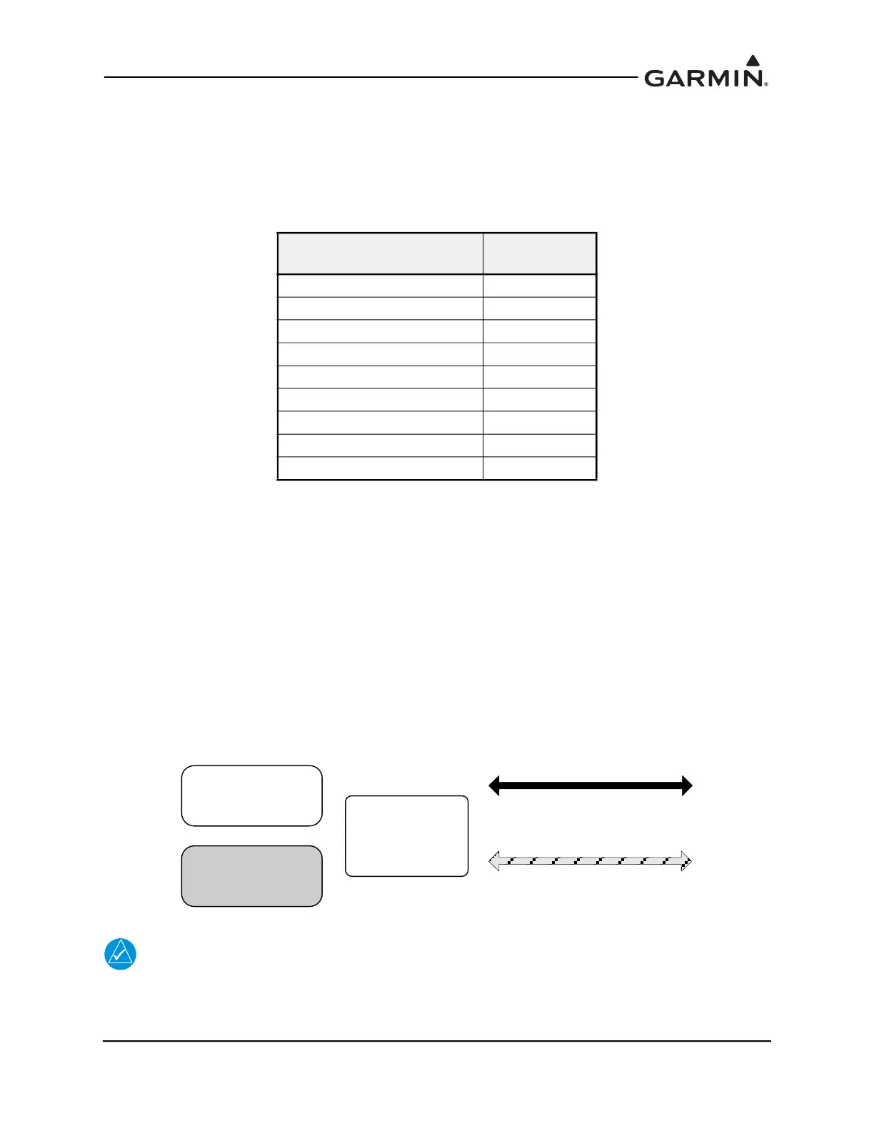
Figure 3-1 HSDB Architecture: Legend
NOTE
The orientation of LRUs and HSDB ports in the following diagrams do not represent the
actual orientation of the installation in the aircraft.
LRU
Number of
HSDB Ports
GI 275 2
GTN 6XX/7XX 4
GTN Xi 4
GTS 8XX 1
GDL 69 series 4
GTX 345 2
GFC 600 2
GPS 175/GNX 375/GNC 355 1
G500/G600 TXi 4
GI 275 STC
OTHER STC
1 HSDB port 1
2 HSDB port 2
Optional connection
if specific LRUs are present
Required connection
if specific LRUs are present

 Loading...


