190-02246-10 GI 275 Part 23 AML STC Installation Manual
Rev. 11 Page 6-9
6. If dual navigation receivers are installed, power off NAV 1 and power on NAV 2.
7. Select NAV2 as the CDI source and repeat steps 3 and 5.
6.3.2.2 NAV Receiver Check – Analog
This check is required for units configured as an HSI, HSI/Standby ADI, MFD (with the CDI page), and
MFD/Standby ADI (with the CDI page). Prior to conducting this check, ensure that the GI 275 has been
calibrated to the NAV receiver in accordance with Section 5.7.3.
1. Verify the NAV1 receiver is turned on and, if dual NAV receivers are installed, ensure the second
NAV receiver (NAV2) is powered off.
2. Select the NAV receiver as the CDI source by touching the CDI button until “VOR” is displayed
in green on the left side of the screen.
3. Tune the NAV receiver to a VOR frequency (it is not necessary that a valid VOR signal is being
received).
4. Using a VOR/ILS test set, generate a 0° FROM radial VOR signal and tune the NAV receiver to
the test frequency.
5. Adjust the course pointer until the deviation is centered and FROM is indicated.
6. Verify that the course pointer setting is 0 ± 4°.
7. Repeat the above steps using VOR FROM signals at 90°, 180°, and 270°. Verify that the course
pointer is within 4° of the simulated VOR bearing.
8. Tune the navigation receiver to a localizer frequency (it is not necessary that a valid localizer
signal is being received).
9. Verify that “LOC” (or “LOC1”/“LOC2” for installations with dual navigators) is displayed.
10. Set the course pointer to the current heading (i.e., straight up on the GI 275 CDI or HSI).
11. Using a VOR/ILS test set, generate a localizer and glideslope signal as specified in Table 6-3.
12. Verify that the course pointer deviation bar and glideslope indications are as specified in
Table 6-3.
13. If dual NAV receivers are installed, power off NAV1 and power on NAV2.
14. Select NAV 2 on the CDI. Repeat the NAV receiver check.
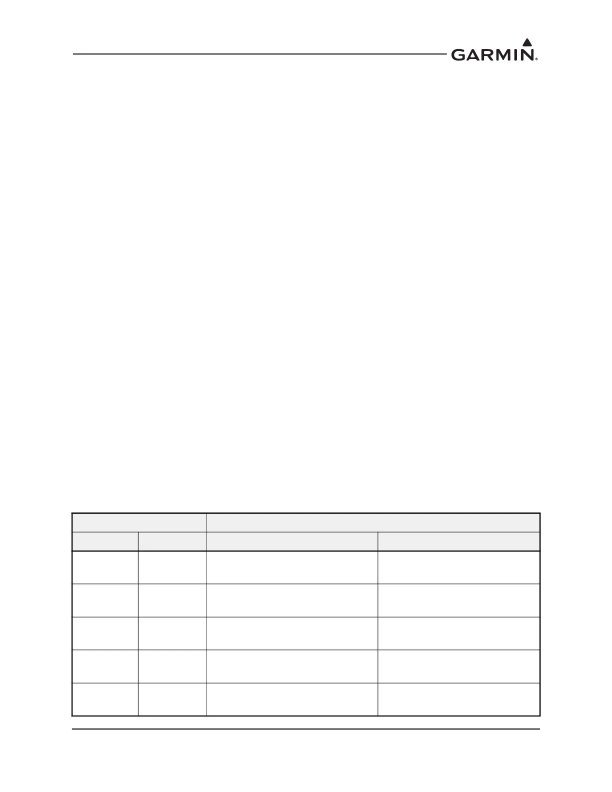
Table 6-3 Localizer/Glideslope Checks
Test Set Setting (DDM) PFD Indication
Localizer Glideslope Localizer Glideslope
0.000 0.000
Centered
(within fuselage on aircraft symbol)
Centered
(covering horizontal white line)
0.078 Right 0.088 Down
Half-scale right
(dev bar inside of first dot)
Half-scale down
(first dot covered by diamond)
0.155 Right 0.175 Down
Full-scale right
(dev bar inside of second dot)
Full-scale down
(second dot covered by diamond)
0.078 Left 0.088 Up
Half-scale left
(dev bar inside of first dot)
Half-scale up
(first dot covered by diamond)
0.155 Left 0.175 Up
Full-scale left
(dev bar inside of second dot)
Full-scale up
(second dot covered by diamond)

 Loading...


