190-02246-10 GI 275 Part 23 AML STC Installation Manual
Rev. 11 Page E-3
E.3 Arc Ranges
E.3.1 Configuration
The information listed in Table E-1 must be obtained for every installation. Figure E-2 illustrates airspeed
tape arc ranges for the GI 275. The POH/AFM column lists a suggested location for obtaining this
information. Arc ranges are typically shown on the airspeed indicator that is being replaced, but should be
checked for accuracy if records indicate it has been replaced. Vne, whether fixed or variable, will be
displayed as the beginning of the red band at the end of the IAS tape.
Figure E-2 shows a visual correlation between arcs defined in POH/AFM Type Data and those configured
in the GI 275.
NOTE
These ranges must match the Type Data (POH/AFM or aircraft specifications) for the
specific aircraft being modified.
NOTE
If the airspeed values are listed in the Type Data (POH/AFM or aircraft specifications) for
both IAS and CAS, use the IAS values.
NOTE
Do not configure two arc ranges to overlap each other. Gaps are acceptable between
ranges, but overlaps are not.
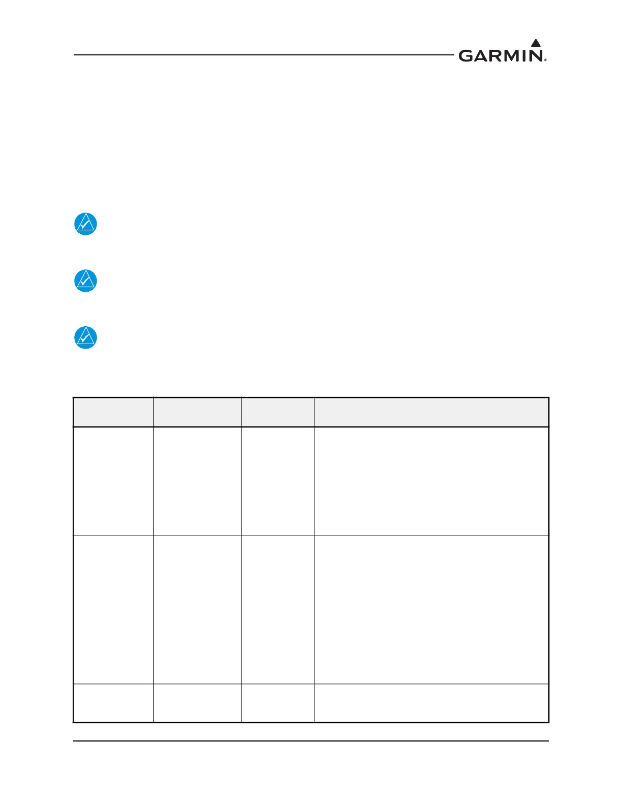
Table E-1 Advanced Airframe-Specific Configuration Data – Arc Ranges
Arc Color Description
POH/AFM
Section
Notes
RED
(LOW SPEEDS)
Low speed
awareness
2 - Limitations
If the aircraft has a defined WHITE or GREEN arc, set
the RED tape to ON. Set the Max value of the RED
tape to the lowest value of the WHITE or GREEN arc
(Vs0). A RED low-speed awareness tape will appear
below the lowest marked stall speed.
If the aircraft does not have a defined WHITE or
GREEN arc, set the RED line to OFF, and enter the
lowest stall speed in the Stall Speed setting at the
bottom of the page.
WHITE
Full flap
operational range
2 - Limitations
Set the Min value to the bottom of the POH/AFM
defined range.
If WHITE and GREEN arcs overlap, set the Max value
to the beginning of the WHITE/GREEN arc.
If WHITE and GREEN arcs do not overlap, set the Max
value to the top of the POH/AFM or aircraft
specification defined range.
If a WHITE arc is not defined by the AFM/POH or
aircraft specifications, set both the Min and Max values
to the aircraft stall speed in the landing configuration
(Vs0). This setting will not display WHITE arc, but the
system needs it to characterize aircraft performance.
HALF WHITE
Standard
operational range
2 - Limitations
If the HALF WHITE arc range is not defined by the
AFM/POH or aircraft specification, set to OFF. This
may sometimes be called a “narrow WHITE arc.”