190-02246-10 GI 275 Part 23 AML STC Installation Manual
Rev. 11 Page G-12
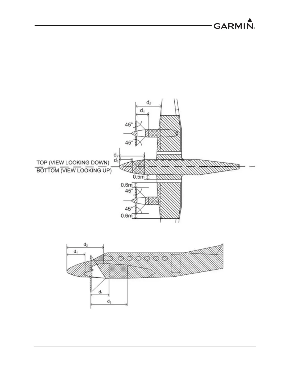
G.2.2.2 Aircraft with Multiple Propellers
Zoning of low- or high-wing aircraft with twin front-mounted propellers is shown in Figure G-10. The text
below assumes the aircraft fuselage and wing are constructed of metal. Note that Zone 2A can overlap onto
the nacelles if they are within 0.6 meters outboard of the fuselage.
Zoning of low- or high-wing aircraft with rear-mounted twin propellers is shown in Figure G-11. The text
below assumes the aircraft fuselage and wing are constructed of metal.
For an empennage with a third engine, the GTP 59 cannot be located in the empennage. Therefore, the
zoning for this third engine area has been omitted from the diagrams below. The GTP 59 and GMU 11/44B
for this aircraft should be located in Zone 3 or Zone 2A on the bottom of the fuselage and wings.
A
B
Figure G-10 Zoning for Front-Mounted Twin Propellers (Low- or High-Wing)

 Loading...


