190-02246-10 GI 275 Part 23 AML STC Installation Manual
Rev. 11 Page 6-29
10. Change the airspeed until the ADI airspeed tape pointer is at the top of the green band/bottom of
the yellow band (Vno).
11. Verify that the top of the green arc/band on the standby ASI and ADI airspeed tape are at the same
airspeed value.
12. Increase the airspeed to the upper red radial/top of yellow arc (Vne).
13. Verify that the red radial on the standby ASI and ADI airspeed tape are at the same airspeed value.
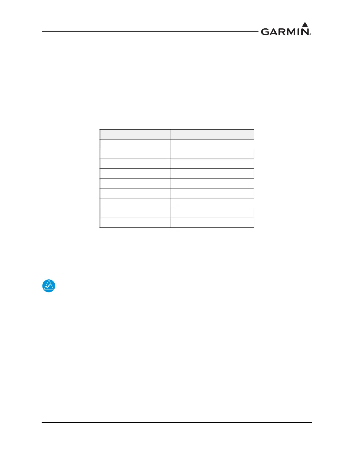
14. Starting at the current airspeed, decrease the airspeed to zero, stopping at each of the airspeeds
listed in Table 6-5 (airspeeds above Vne should not be checked), verifying that the ADI and
standby ASI airspeed values are within the tolerances indicated in Table 6-5.
Table 6-5 Airspeed Test Points
6.5.1.1.2 Advanced Airspeed Tape Setting
If the Airspeed Configuration Type is set to Advanced, refer to Appendix E. Set the Airspeed
Configuration Type on the Airspeed Configuration page (Setup → Airframe Configuration → Airspeed
Configuration). Verify correct operation of the ADC as follows.
NOTE
If the ADC and standby airspeed indicator are on separate pitot-static systems, it is
recommended to set up the test set so that both systems can be tested at the same time, or
separate tests must be completed for each system.
1. Power on all GI 275s in the system in Normal mode.
2. Using a pitot-static test set, increase the airspeed until the ADI airspeed tape pointer is at the
bottom of the white band (Vs0).
3. Verify that the bottom of the white arc/band on the standby ASI and ADI airspeed tape are at the
same airspeed value.
4. Increase the IAS throughout the range of the ASI. Stop at the limits of all Arc Ranges and at all
Marking values configured per the instructions in Table E-1 and Table E-4.
5. Verify that the ranges and markings on the standby ASI and ADI are located at the same airspeed
values. The last value verified should be the beginning of the red overspeed range (Vne/Vmo/
Mmo).
Test Set Airspeed (kt) ADI Allowed Tolerance (kt)
50 ±5.0
80 ±3.5
100 ±2.0
120 ±2.0
150 ±2.0
180 ±2.0
210 ±2.0
250 ±2.0
290 ±3.0

 Loading...


