190-02246-10 GI 275 Part 23 AML STC Installation Manual
Rev. 11 Page 3-26
Notes:
[1] Not installed under this STC.
[2] Refer to Appendix Section C.19 for STC compatibility.
[3] Interface a single OAT probe to one GEA Engine Adapter for standalone EIS installations only.
External data sources intended for use with the GI 275 must be checked for compatibility before
installation. These checks must be accomplished in accordance with procedures and data furnished by the
equipment manufacturer.
3.4.2 Attitude and Air Data
ADAHRS is required for ADI and standby functionality. The GTP 59 OAT is optional; however, without
the installation of the GTP 59, standard rate turn indicators and outside air temperature will not be present.
It is recommended to install a GTP 59 with a GI 275 displaying attitude information. A separate GMU 11
or GMU 44B Magnetometer is required to take credit for the compensated heading.
3.4.3 GEA 24/110 Engine Adapter
A GEA 24 or GEA 110 is required for each aircraft engine if EIS is installed. EIS sensor options and
configurations are presented in Appendix Section C.19. Select the sensors required to support the EIS
gauges determined in Section 3.2.3. Specific sensors are discussed below.
1. EGT/TIT and CHT
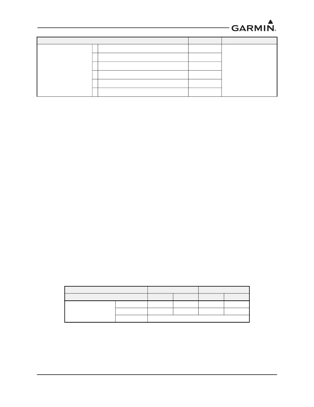
The number of probes required for aircraft installation is shown in Table 3-23. The Primary EGT/TIT
and CHT indication, if applicable, must be retained. The primary EGT/TIT probe can be changed, but
the installed location must remain the same.
Table 3-23 EGT and CHT Probe Quantity
All thermocouple lead wires must match the thermocouple type (K- or J-Type). Do not crimp
connector pins to a single-strand thermocouple wire, as the wire is too thick; only use a multi-strand
lead wire for connector pins. Copper wire must never be used for thermocouples.
2. Oil Pressure Sensor
Select the most suitable sensor from Table C-20.
Engine Sensors
(continued) [2]
Carb Temp Sensor
Fuel Pressure Sensor
Fuel Flow
Fuel Quantity [1]
Shunt (Amperage) [1]
OAT [3]
Aircraft Engines Single Twin
Cylinders per engine 4 6 4 6
P
ROBE QTY
EGT 4 6 8 12
CHT 4 6 8 12
P
RIMARY AS REQUIRED
Equipment Selection Notes Location

 Loading...


