190-02246-10 GI 275 Part 23 AML STC Installation Manual
Rev. 11 Page 1-3
1.2 System Overview
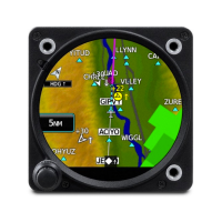
The GI 275 is a multi-function electronic instrument display capable of operating as a standalone display.
It features a bright, sunlight readable, 3⅛-inch diameter color display that is sized to fit in a standard
instrument cutout.
The GI 275 Multi-Function Instrument can be configured as the following indicator types:
• Primary Attitude Display Indicator (attitude, altitude, airspeed, and heading)
• Standby Attitude Display Indicator (attitude, altitude, airspeed, and heading)
• Horizontal Situational Indicator (HSI) and Enhanced Horizontal Situational Indicator (EHSI)
• Engine Instrument System Indicator (EIS)
• Multi-Function Display Indicator (MFD)
The following dedicated pages are available on a GI 275 MFD or MFD/Standby ADI:
• CDI (MFD only)
• ADI (MFD/Standby ADI only)
• HSI
• Stormscope
• Terrain
• Moving Map
• Radar Altimeter
• Traffic
• Weather
• Transponder
If the GI 275 is configured as a Primary ADI, no other pages can be displayed.
Primary instruments, such as the Standard Turn Rate Indicator, must be retained unless a Standby ADI is
installed. A GTP 59 OAT probe is required to be installed to display standard turn rate indices on the ADI.
Refer to Section 2 for limitations.
When the GI 275 provides altitude, airspeed, attitude, or heading, the internal ADAHRS is required as the
primary sensor. The backup battery is available for all GI 275 units as an option, and is required for
standby displays that are powered by the aircraft’s primary electrical power source.
The GI 275 EIS uses the GEA 24 or the GEA 110 adapter and sensors to replace various engine
instruments and provide indication of engine parameters. For a single engine, a single GI 275 with multiple
pages can be used; however, all alerting gauges must fit on the primary gauge page. If a GEA 110 is
installed as part of the GI 275 system, the -01 model of the GEA 110 must be used.
For twin-engine EIS, each engine must have a dedicated GEA 24/110 and each engine must have separate
GI 275 indicators. Only one indicator is permitted per engine. If multiple indicators are needed to display
all primary alerting gauges, then certain existing gauges must be retained instead.
EIS units may not share a GEA 110/24 interface with G500/600 TXi or G3X systems, respectively. If using
a GI 275 for EIS, then the EIS interface may only be connected and displayed on the GI 275 system, and
may not be connected or displayed on TXi or G3X systems.

 Loading...