190-02246-10 GI 275 Part 23 AML STC Installation Manual
Rev. 11 Page 4-64
4.7.2 GEA 110
The GEA 110 is mounted directly to the airframe in the aircraft fuselage or the engine compartment with or
without an optional installation tray. If the aircraft does not have any suitable platform for the GEA 110,
the shelf or support structure shown in Figure 4-43 can be used to mount the GEA 110.
Installing the GEA 110 in the fuselage or engine compartment offers the convenience of reduced wire
length when connecting engine sensors. The GEA 110 can be mounted at any orientation, but a vertical
orientation with connectors pointing down is preferred in locations exposed to moisture or fluids. Sealed
connector kit (P/N 011-03527-51) must be used if the GEA 110 can come into contact with fluids or when
mounted in the engine compartment.
The GEA 110 must not be placed directly below fluid lines (e.g., fuel, oil, hydraulic). If it is mounted close
to the aircraft powerplant, the GEA 110 must not block or alter the flow of air required for engine cooling.
It must be installed as far away as practical from heat sources.
If provisioned by the aircraft structural repair manual or standard practices manual, the GEA 110 can be
mounted on the engine firewall or on a bulkhead that is supporting the powerplant installation. The
GEA 110 wiring must be routed through existing pass-through holes in the firewall or use existing
bulkhead connectors. Separate airworthiness approval is required for added holes in engine firewall.
GEA 110 electrical connector screws must be torqued to 5 ± 0.5 in-lbf.
Table 4-11 GEA 110 Weight and Size
Notes:
[1] Includes tray.
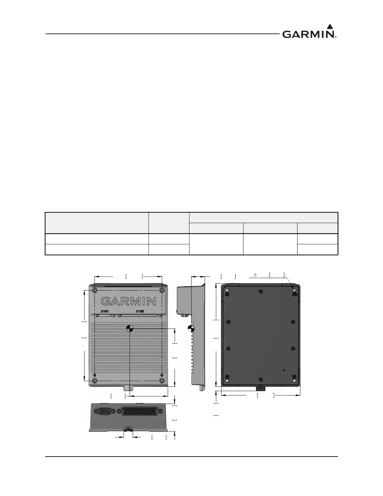
Figure 4-46 GEA 110 Dimensions
Item
Weight
lb. (kg)
Dimensions in. (mm)
Height Width Depth
GEA 110 unit 1.21 (0.55)
7.75 (196.8) [1] 4.81 (122.2) [1]
1.63 (41.4)
GEA 110 with tray and connector 2.11 (0.96) 2.13 (54.1)
LQ
PP
LQ
PP
LQ
PP
LQ
PP
LQ
PP
LQ
PP
LQ
PP
LQ
PP
;
LQ
PP
LQ
PP
LQ
PP

 Loading...


