190-02246-10 GI 275 Part 23 AML STC Installation Manual
Rev. 11 Page 5-41
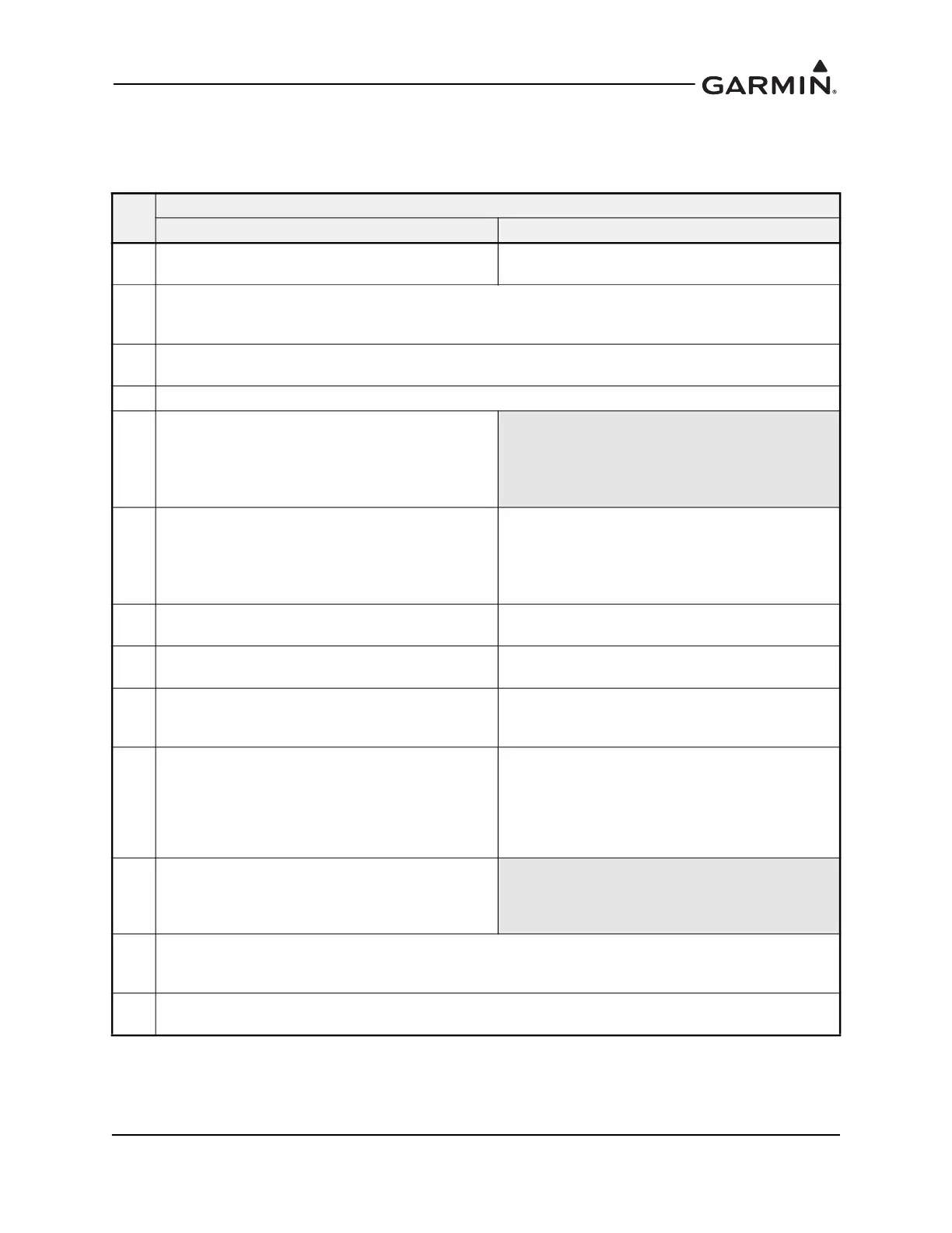
Lighting Bus Configuration - Enhanced Lighting De-selected
The Display Lighting and the Knob Lighting curves must be set individually as noted in Table 5-47.
Table 5-47 Lighting Bus Configuration Procedure
Step
Lighting Bus Curve
Display Knob
1
Under Source Selection, set Lighting Bus as the
source for Display Source.
Under Source Selection, set Lighting Bus as the
source for Knob Source.
2
Under Lightning Bus Configuration, set the Input Type to match the aircraft lighting bus voltage and the
Response Time to a low level (e.g., 0 sec) to allow the display to adjust more quickly to dimmer bus input
changes.
3
Follow steps 4 - 12 to achieve consistency between all cockpit lighting. Figure 5-12 shows the primary
settings on both the display lighting and the keys lighting curves.
4 Simulate night conditions in the cockpit.
5
Set the Transition to 5%. Below this source input
value, the photocell will override the dimmer bus for
display backlighting control.
NOTE: This also allows the photocell to function as a
backup in the event of a lighting bus failure.
6
Turn the dimmer bus knob to its minimum setting or
below the transition % value.
NOTE: Steps 7 - 9 and 11 will set the photocell
functionality when the lighting bus is below the
transition % value.
Turn the dimmer bus knob to its minimum setting.
7
If the display is too bright, lower the Min Level and/or
adjust the Slope to achieve the desired brightness.
If the knob is too bright, lower the Min Level and/or
adjust the Slope to achieve the desired brightness.
8
If the display is too dim, increase the Min Level to
achieve desired levels.
If the knob is too dim, increase the Min Level to
achieve desired levels.
9
With the dimmer bus still off or below the transition %
value, adjust the Offset such that the display remains
readable.
With the dimmer bus still off, adjust the Offset such
that the bezel key remains visible.
10
Slowly move the dimmer bus knob towards its
maximum setting. Observe the rate of change
between the display lighting, bezel key lighting, and
any other cockpit illuminated information over the full
range above transition % value of the dimmer bus.
Adjust the Slope and/or Offset to obtain consistency.
Slowly move the dimmer bus knob towards its
maximum setting. Observe the rate of change
between the display lighting, bezel key lighting, and
any other cockpit illuminated information over the full
range of the dimmer bus. Adjust the Slope and/or
Offset to obtain consistency.
11
With the dimmer bus off, simulate direct sunlight
conditions in the cockpit. If the brightness is below
the desired level, adjust the Slope setting to achieve
maximum desired brightness.
12
Adjust the Response Time to smooth changes to brightness, as required. This can be done from the Lighting
Bus Configuration page (Setup → Lighting → Lighting Bus Configuration). You will need to save your
configuration when exiting the Lighting Curve Configuration page.
13
Verify that adjustments made in the preceding steps are appropriate and functional for all expected lighting
conditions.

 Loading...


