190-02246-10 GI 275 Part 23 AML STC Installation Manual
Rev. 11 Page 4-48
4.6.1.4 GMU 44B Installation
When installing the GMU 44B, ensure the bend radius of the pig tail harness must be at least 1.5 inches.
Additionally, there must be at least 3 inches of space above the GMU 44B for removal.
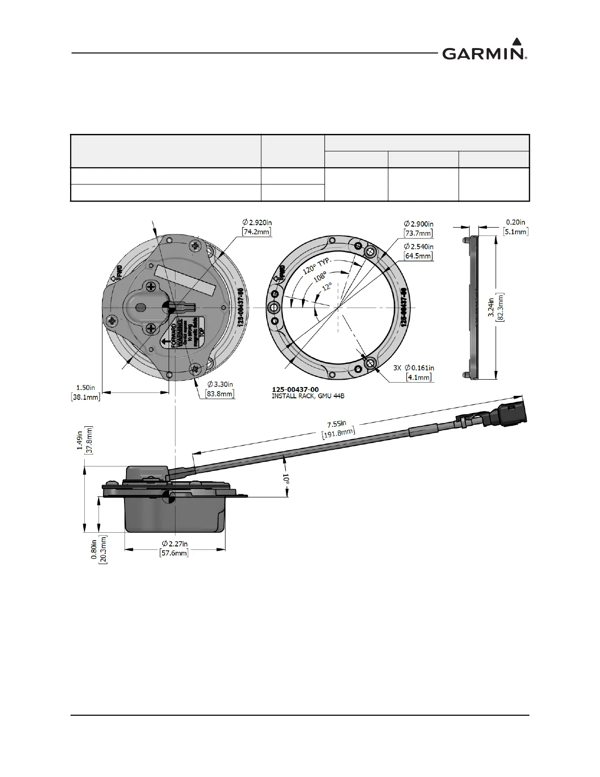
Table 4-8 GMU 44B Weight and Size
Figure 4-32 GMU 44B Dimensions
(shown with rack)
The GMU 44B Universal Mount offers flexibility in installation. Combined with the GMU 44B Install
Rack, it allows for convenient heading and level alignments.
A custom bracket can be fabricated in lieu of using the GMU 44B Universal Mount. The bracket must be
fabricated in accordance with the requirements applicable to the replacement equipment shelf detailed in
Figure 4-34 and be a minimum of 0.032 inches thick. The GMU 44B install rack must be installed
regardless of whether the GMU 44B Universal Mount or custom bracket is used.
Item
Weight
lb. (kg)
Dimensions in. (mm)
Height Diameter Flange
GMU 44B unit only (P/N 011-04201-00)
0.30 (0.14)
1.49 (37.8) Ø2.27 (57.6) Ø3.30 (83.8)
GMU 44B w/install rack and connector
0.39 (0.18)

 Loading...


