Home
Garmin
Avionics Display
GI 275
Garmin GI 275 User Manual
4
of 1
of 1 rating
531 pages
Give review
Manual
Specs
To Next Page
To Next Page
To Previous Page
To Previous Page
Loading...
190-02246-10
GI 275 Part
23 AML STC Installation Manual
Rev. 11
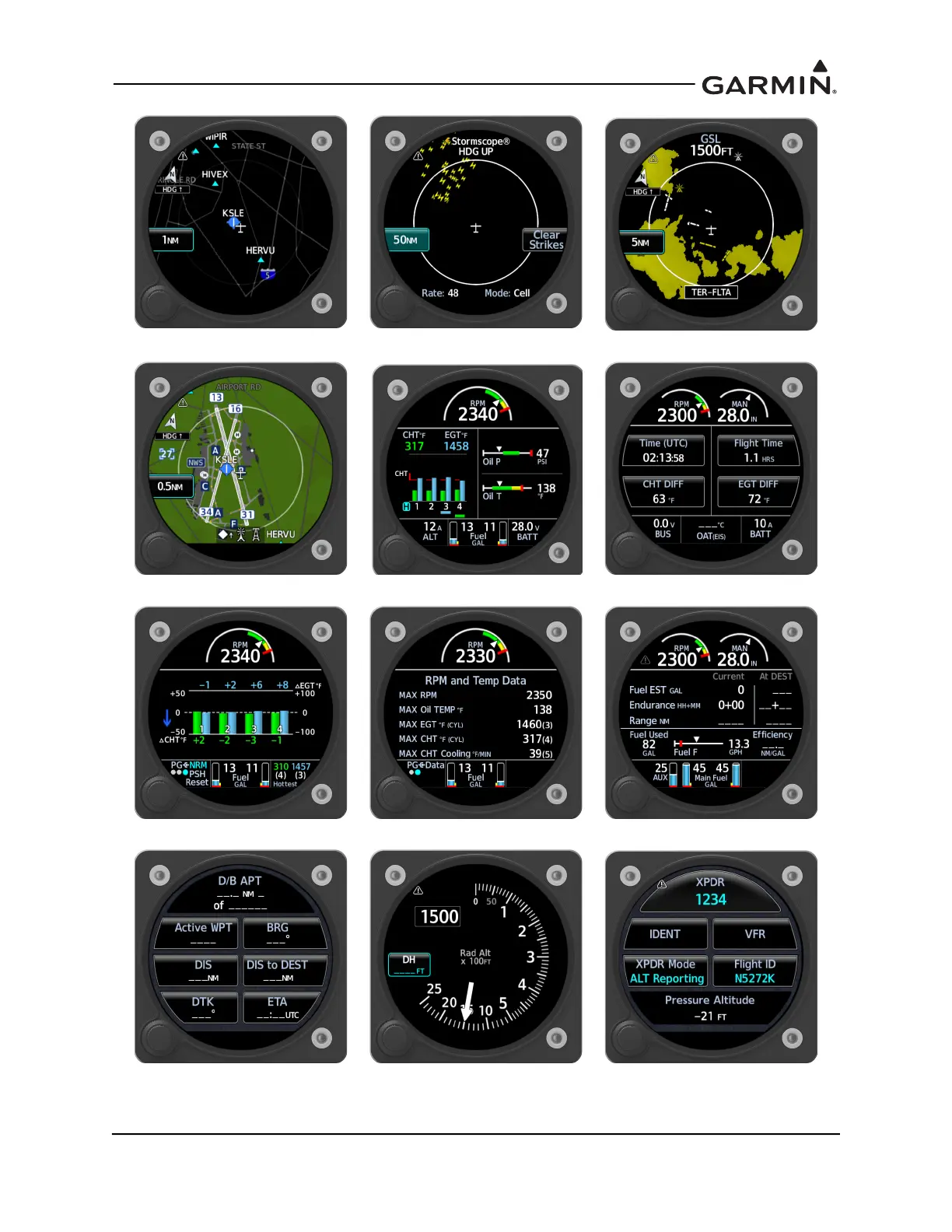
Page 5-50
Figure 5-19 GI 275 Norm
al Mode Pages
FIS-B We
ather page
Stormscope page
T
errain page
Map page
Main EIS page
AUX E
IS page
CHT/EGT page
S
ummary page
Fue
l page
MFD Data page
Radar
Al
timeter page
T
ransponder page
227
229
Table of Contents
Table of Contents
13
STC Applicability
26
System Overview
27
Figure 1-1 GI 275 System Installation (before and after Example)
28
Table 1-1 Garmin Manuals and References for GI 275 System
29
Table 1-2 Garmin Installation Manuals for Other Systems
29
Table 1-3 Technical References
30
Table 1-4 GI 275 Variant Functionality
30
Figure 1-2 GI 275 Primary ADI
31
Table 1-5 Primary ADI Features by Unit Selection
32
Figure 1-3 GI 275 Horizontal Situation Indicator
34
Table 1-6 HSI Features by Unit Selection
35
Figure 1-4 GI 275 Multi-Function Display Indicator
36
Table 1-7 MFD Features by Unit Selection
37
Table 1-8 CDI Features by Unit Selection
38
Figure 1-5 GI 275 Course Deviation Indicator
38
Figure 1-6 GI 275 Standby Indicator
39
Table 1-9 Standby Indicator Features by Unit Selection
40
Figure 1-7 GI 275 Single-Engine EIS Interfaces
41
Table 1-10 EIS Features by Unit Selection
41
Figure 1-8 GI 275 Twin-Engine EIS Interfaces
42
Equipment
44
Figure 1-9 VFR GPS Antenna
44
Figure 1-10 GMU 44B Magnetometer
45
Figure 1-11 GMU 11 Magnetometer
45
Figure 1-12 GTP 59 OAT Probe
45
Figure 1-13 GEA 24 Engine Adapter
46
Figure 1-14 GEA 110 Engine Adapter
46
Figure 1-18 Oil Temperature Probe
47
Figure 1-16 EIS Annunciator (Separate)
47
Figure 1-17 Carburetor Temperature Probe
47
Figure 1-15 EIS Annunciator (Single)
47
Figure 1-19 Fuel Flow Transducer FT-60 (Left) and FT-90 (Right)
48
Figure 1-20 Brass (Left) and Stainless Steel (Right) Pressure Sensors
48
Figure 1-21 Backup Battery
49
Figure 1-22 GSB 15 Variants
49
System Architecture Examples
50
Figure 1-23 GI 275 Primary ADI and Twin-Engine EIS
50
Figure 1-24 GI 275 Primary ADI, Reverting Hsi/Standby ADI, and EIS
51
Figure 1-25 GI 275 Primary ADI, HSI, and MFD
52
Figure 1-26 GI 275 Primary ADI, Reverting Mfd/Standby ADI, and HSI
53
Figure 1-27 GI 275 Primary ADI, Reverting Mfd/Standby ADI, HSI, and Single-Engine EIS
54
Figure 1-28 GI 275 Primary ADI, Reverting Hsi/Standby ADI, MFD, and EIS
55
Figure 1-29 KI 256 and KI 525 Replacement
56
2 Limitations
57
General Installation
58
Installation Limitations
58
Primary Attitude Direction Indicator (ADI)
58
System
58
Eis
59
Standby Indicator
59
GMU Class Restrictions
60
GPS Source Limitations
60
Autopilot Interface
61
Transponder Control
61
USB Connection
61
Vfr Gps
61
Class IV Aircraft
62
Part 121/135 Operations
62
Operational Limitations
63
3 Preparation
64
Garmin
65
Materials and Parts
65
Table 3-1 GI 275 Units
65
Table 3-2 GI 275 Connector Kits
65
Table 3-3 GI 275 Lrus
66
Table 3-4 LRU Installation Kits
66
Commercial
67
Table 3-5 HSDB Cables
67
Table 3-6 EIS Annunciator
68
Special Tools Required
69
Table 3-7 Recommended Crimp Tools
69
GI 275 Installation Requirements
70
Power Distribution
70
Table 3-8 Power Distribution
70
Table 3-10 Circuit Breaker Labels - Single Essential Bus
71
Table 3-9 Switch Labels
71
Table 3-11 Circuit Breaker Labels - Independent Essential Busses
72
Standby Instruments
73
Table 3-12 GI 275 Standby ADI Restrictions Per System
73
Engine Indication System (EIS)
74
Table 3-13 GI 275 Hsi/Standby ADI Restrictions
74
Table 3-14 Required Gauges for EIS
75
Table 3-15 Additional Gauges
75
Table 3-16 Available EIS Parameters
76
Display Lighting Control
77
GPS Requirements
77
Figure 3-1 HSDB Architecture: Legend
78
HSDB Architecture
78
Table 3-17 Garmin LRU HSDB Port Summary
78
Figure 3-2 HSDB Architecture: Primary ADI
79
Figure 3-3 HSDB Architecture: Primary ADI with GFC 600 Autopilot
79
Figure 3-4 HSDB Architecture: EIS
79
Figure 3-5 HSDB Architecture: MFD
80
Figure 3-6 HSDB Architecture: Primary ADI with GFC 600 and Hsi/Standby ADI
80
Figure 3-7 HSDB Architecture: Primary ADI with GFC 600, Hsi/Standby ADI, and EIS
81
Figure 3-8 HSDB Architecture: Primary ADI, Mfd/Standby ADI, HSI, and EIS
81
Figure 3-9 HSDB Architecture: Primary ADI, Mfd/Standby ADI, HSI, EIS, Co-Pilot ADI
82
GPS Source
83
Interfaces to Other Equipment
83
Navigation Receiver
83
Radar Altimeter
83
Table 3-18 Traffic Interface
83
Traffic
83
Audio Panel
84
Autopilot
84
Data Link
84
Stormscope
84
Transponder Control
84
Table 3-19 Autopilots and Interfaces
85
External TAWS
86
Aircraft Eligibility Checklist
87
Selection of GI 275 System Components
87
Table 3-21 Aircraft Eligibility Checklist
87
Table 3-22 GI 275 System Components
88
Attitude and Air Data
89
GEA 24/110 Engine Adapter
89
Table 3-23 EGT and CHT Probe Quantity
89
Electrical Load Analysis
92
Table 3-24 LRU Current Draw
92
Table 3-25 Net Electrical Load Change Calculation Example (14 VDC Aircraft)
93
Figure 3-10 Ammeter Placement for Current Measurement
95
Figure 3-11 Tabulated Electrical Load Form
96
Figure 3-12 Example of Completed Tabulated Electrical Load Form
98
Battery Capacity Analysis
100
4 Installation
102
Wire Routing and Installation
103
Shielded Cable Preparation
104
Figure 4-1 Shield Termination Methods
105
Pitot-Static Routing
106
Figure 4-2 Pitot-Static Connections for Single GI 275 Installation
107
Figure 4-4 Pitot-Static Connections for Dual GI 275 Installation
109
Figure 4-5 Pitot-Static Connections for Dual GI 275 Installation
110
Equipment Bonding
111
Table 4-1 Bonding Requirements
111
Aluminum Surface Preparation
112
Vibration Mounts
112
Figure 4-6 Example of Pilot Field-Of-View Installation
113
Instrument Panel Installations
113
Figure 4-7 Example of GI 275S in "Six Pack" Instrument Panel (Single-Engine)
114
GI 275 Multifunction Indicator
114
Figure 4-8 Example of GI 275S in "Six Pack" Instrument Panel (Multi-Engine)
115
Figure 4-9 Example of GI 275S in Non-"Six Pack" Instrument Panel (Single-Engine)
115
Figure 4-10 GI 275 Multifunction Indicator Dimensions
116
Table 4-2 GI 275 Multifunction Indicator Weight & Size
116
Figure 4-11 Installation of GI 275 Display in the Instrument Panel
118
Figure 4-12 GI 275 Cutout
120
Backup Battery
122
Figure 4-13 Backup Battery Dimensions
122
Table 4-3 Backup Battery Weight and Size
122
Figure 4-14 GI 275 Backup Battery Installation
123
EIS Annunciator
124
Figure 4-15 EIS Caution and Warning Annunciator Installation
124
Figure 4-16 EIS Caution and Warning Annunciators Installation
125
Gsb 15
126
Table 4-4 GSB 15 Weight and Size
126
Figure 4-17 GSB 15 Dimensions
127
Figure 4-18 GSB 15 Cutout Dimensions
128
Figure 4-19 GSB 15 Cutout Installation
129
Figure 4-20 GSB 15 Installation with Mounting Kit (2.25-Inch Cutout)
130
Figure 4-21 GSB 15 Installation with Mounting Kit (3.125-Inch Cutout)
131
Figure 4-22 GSB 15 Decorative Cover Installation
132
Backshell Assembly
133
Figure 4-23 Jackscrew Backshell and Shield Block Assembly
134
Figure 4-24 Shield Block Termination on Jackscrew Backshell Assembly
135
Configuration Module Installation
136
Figure 4-25 Jackscrew Backshell Assembly
136
GSB 15 Connector Assembly
137
Display Sensors
138
Gmu 11/44B
138
Table 4-5 GMU Recommended Distance from Sources of Magnetic Interference
138
Figure 4-26 Magnetic Interference Test Harness
140
Table 4-6 Example Magnetic Interference Test Sequence List
142
Figure 4-27 GMU 11 Dimensions
143
Table 4-7 GMU 11 Weight and Size
143
Figure 4-28 GMU 11 Mounting Hardware
144
Figure 4-29 Example GMU 11 Mounting Shelf
145
Figure 4-30 GMU 11 Overbraid Installation
147
Figure 4-31 GMU 11 Overbraid Termination
148
Figure 4-32 GMU 44B Dimensions
149
Table 4-8 GMU 44B Weight and Size
149
Figure 4-33 GMU 44B Installation (Universal Mount Example)
150
Figure 4-34 GMU 44B Installation (Fabricated Bracket Example)
151
Figure 4-35 GMU 44 Series Connector Wire Overbraid Installation
153
Figure 4-36 GTP 59 OAT Probe Dimensions
154
Gtp 59
154
Figure 4-37 GTP 59 Installation in Metallic Aircraft
155
Figure 4-38 GTP 59 Installation in Composite Aircraft (Non-Conductive Access Panel)
156
Figure 4-39 GTP 59 Installation in Composite Aircraft (Conductive Access Panel)
157
Backup GPS Antenna
158
Figure 4-40 Backup GPS Antenna Dimensions
158
Table 4-9 Backup GPS Antenna Weight and Size
158
Figure 4-41 Backup GPS Antenna Installation (Non-Removable Installation Example)
159
Figure 4-42 Backup GPS Antenna Installation (Removable Installation Example)
160
Engine Indicating System
161
Gea 24
161
Figure 4-43 Example Support Structure
162
Table 4-10 GEA 24 Weight and Size
162
Figure 4-44 GEA 24 Dimensions
163
Figure 4-45 GEA 24 Mounting Hardware
164
Figure 4-46 GEA 110 Dimensions
165
Gea 110
165
Table 4-11 GEA 110 Weight and Size
165
Figure 4-47 GEA 110 Installation (Mounted Directly to Airframe Example)
166
Figure 4-48 GEA 110 Installation (Mounted on a Tray Example)
167
Carburetor Air Temperature
168
Figure 4-49 Carburetor Temperature Sensor Installation Example
168
Figure 4-50 Oil Temperature Sensor Installation Example
169
Oil Temperature
169
Pressure
170
Figure 4-51 Brass Sensor Installation, Coupling Mount Example
171
Figure 4-52 Stainless Steel Sensor Installation, Housing Mount Example
172
Figure 4-53 Fuel Flow Installation Configurations
173
Fuel Flow
173
Figure 4-54 Example Fuel Flow Transducer Installation
175
Figure 4-55 Fuel Flow Overbraid
176
Figure 4-56 Tcm/Bendix Magneto Vent Hole
176
Rpm
176
CHT, EGT, TIT Probes
177
Eis Oat
177
Figure 4-57 Slick Magneto Vent Hole
177
Table 4-12 Weight and Balance Calculation Example
178
Weight and Balance
178
5 System Configuration
179
Figure 5-1 System Configuration Flow
181
System Configuration Preparation
181
Entering Configuration Mode
182
Figure 5-2 Entering the Configuration Menu
182
Figure 5-3 Software Update
183
Loader Card
183
Software / Configuration
183
Config Options
184
Unit ID
185
Unit Type
185
Airframe Type
186
System ID Source
186
Unit Configuration
186
Figure 5-4 Interface and Ports/Config Selections
188
Interfaces
188
GI 275S Installed
189
Wireless
189
Adc
190
Table 5-1 ADC Interfaces and Configuration Settings
190
Table 5-2 ADC Configuration Priority
190
Ahrs
191
Table 5-3 AHRS Interfaces and Configuration Settings
191
Table 5-4 AHRS Configuration Priority
192
Gps
193
Table 5-5 GPS Interfaces and Configuration Settings
193
Vfr Gps
193
Nav
194
Table 5-6 NAV Interfaces and Configuration Settings
194
Autopilot
195
Radar Altimeter
195
Table 5-7 RAD ALT Interfaces and Configuration Settings
195
Table 5-10 Bendix M-4C/M-4D Autopilot Configuration
196
Table 5-8 Garmin GFC 500 Autopilot Configuration
196
Table 5-9 Garmin GFC 600 Autopilot Configuration
196
Table 5-11 Century 2000 Autopilot Configuration
197
Table 5-12 Century 21/31 Autopilot Configuration
197
Table 5-13 Century 41 Autopilot Configuration
197
Table 5-14 Century II/III Autopilot Configuration
198
Table 5-15 Century IV AC Autopilot Configuration
198
Table 5-16 Century IV DC Autopilot Configuration
198
Table 5-17 Cessna AC Autopilot Configuration
199
Table 5-18 Cessna DC Autopilot Configuration (1000
199
Table 5-19 Cessna DC Autopilot Configuration
200
Table 5-20 Collins AP-106/107 Autopilot Configuration
200
Table 5-21 Honeywell (Bendix/King) KAP 150/KFC 150 Autopilot Configuration
201
Table 5-22 Honeywell (Bendix/King) KAP 100/200 Autopilot Configuration
201
Table 5-23 Honeywell (Bendix/King) KAP 140 Autopilot Configuration
201
Table 5-24 Honeywell (Bendix/King) KFC 225 Autopilot Configuration
202
Table 5-25 Honeywell (Bendix/King) KFC 250-4" HSI Autopilot Configuration
202
Table 5-26 Honeywell (Bendix/King) KFC 200/250-3" HSI Autopilot Configuration
203
Table 5-27 Honeywell (Bendix/King) KFC 300 Autopilot Configuration
203
Table 5-28 Sperry SPZ-200A/500 Autopilot Configuration
204
Table 5-29 S-TEC 20/30/40/50/60-1 Autopilot Configuration
204
Table 5-30 S-TEC 60-2/65/60 PSS Autopilot Configuration
205
Table 5-31 S-TEC 55X Autopilot Configuration
205
AHRS Emulation
206
Table 5-32 S-TEC 55 Autopilot Configuration
206
Table 5-33 AHRS Emulation Configuration Settings
206
Table 5-34 Transponder Configuration Settings
206
Transponder
206
Eis
207
Table 5-35 EIS/GEA Configuration Settings
207
Table 5-36 Engine Annunciator Configuration Settings
207
Table 5-37 Traffic System Configuration Settings
208
Traffic
208
Table 5-38 GDL 69 Configuration Settings
209
General Purpose Discrete in
210
General Purpose Discrete out
210
PFD Sync
210
Stormscope
210
Table 5-39 Stormscope Configuration Settings
210
Table 5-40 PFD Sync Configuration Settings
210
Table 5-41 General Purpose Discrete in Settings
210
Table 5-42 General Purpose Discrete out Settings
210
Airspeed Switches
211
General Purpose ARINC 429 (A429) out
211
General Purpose RS-232 out
211
Table 5-43 General Purpose A429 Output Settings
211
Table 5-44 General Purpose Serial Port Setting
211
Airframe Configuration
212
Figure 5-5 Airframe Config Page
212
Figure 5-6 ADI Styles
212
Setup
212
Figure 5-7 Basic (Left) and Advanced (Right) Airspeed Configuration Type Settings
214
Figure 5-8 User-Configurable Airspeed Markings
214
Table 5-45 Airframe-Specific Configuration Data - Configuration Type Basic Setting
215
Figure 5-9 Lighting Page
216
Lighting
216
Table 5-46 Photocell Configuration Procedure
217
Figure 5-10 Lighting Curve Slope Configuration
218
Figure 5-11 Cutoff Percentage Configuration
218
Table 5-47 Lighting Bus Configuration Procedure
219
Figure 5-12 Display Lighting (Left) and Knob Lighting (Right) Curves
220
Table 5-48 Photocell Configuration Procedure - Enhanced Lighting
220
Figure 5-13 Enhanced Lighting Mode Example Photocell
221
Table 5-49 Lighting Bus Configuration Procedure - Enhanced (Display)
221
Figure 5-14 Enhanced Lighting Mode Example Lighting Bus - Display
222
Figure 5-15 Selection between Lighting Bus and Photocell Backup Curves
222
Figure 5-16 Vertex Adjustment Dialog Box
223
Table 5-50 Lighting Bus Configuration Procedure - Enhanced (Knob)
223
Figure 5-17 Page Config Page - Mfd/Standby ADI (Left) and EIS (Right)
224
Page Configuration
224
Figure 5-19 GI 275 Normal Mode Pages
228
Sensors
229
Figure 5-20 External ADC/AHRS Sensor Configuration Example
230
Audio Alert Config
231
Table 5-51 Terrain/Taws Setting
231
Table 5-52 TAWS Airframe-Specific Configuration Data
231
Terrain/Taws
231
Miscellaneous
232
Battery
233
Ownship Icon Configuration
233
Eis
234
Engine
234
Table 5-53 EIS Configuration - Engine
235
Table 5-54 Cruise RPM Setting
235
Figure 5-21 Sensor Menu Example
236
Sensors
236
Figure 5-22 TIT Sensor Configuration Example
237
Table 5-55 Fuel Flow K-Factor
239
Pages
240
Table 5-56 CHT/EGT Page Advanced Settings
240
Gauges
241
Table 5-57 Original Gauge Settings
242
Table 5-58 Additional Gauge Settings
242
Figure 5-23 Gauge Configuration Example
243
Figure 5-24 Gauge Range Marking Example
244
Table 5-59 Gauge Minimum and Maximum Ranges
244
Diagnostics
245
Figure 5-25 Side Text Example
245
Fuel
245
Attitude/Heading Calibration Tests
246
Calibration/Checks
246
Autopilot Calibration
247
Figure 5-26 KAP 100 & KFC/KAP 150 Test Harness
248
Table 5-60 Extension Harness Parts
248
Figure 5-27 KFC 200 Test Port
251
Backup Battery Test
256
Composite NAV Calibration
256
Fuel
257
Table 5-61 Fuel Page Settings
257
Table 5-62 Fuel Quantity Calibration Settings
258
Figure 5-28 Fuel Quantity Calibration Page
260
Figure 5-29 Fuel Quantity Calculation Procedure
260
External Systems
261
Stormscope Config Status
261
Ahrs & Adc
262
Backup Battery Status
262
CAN Network
262
Diagnostics
262
Discrete Inputs
262
Discrete Outputs
262
HSDB Status
262
Temp/Pwr Stats
262
Vfr Gps
262
Analog Inputs
263
Arinc 429
263
Clear Config
263
Factory Reset
263
Gdl69
263
Gfc 500
263
Device Info
264
Devices Online
264
Maintenance
264
System Info
264
Table 5-63 LRU Status Indicators
264
Restart Options
265
Wireless Connectivity
266
Automatic Database Updates
267
Database Loading
267
Database Updates Via USB
268
Transferring Databases Via Database Concierge (Wi-Fi)
268
Feature Enablement
269
GI 275 Databases
269
Table 5-64 Database Summary
269
6 System Checkout
270
Checkout Log
271
Table 6-1 Checkout Log
271
Configuration Ground Checks
274
Device Info
274
GSB 15 Connection Check
274
LRU Status Check
274
Interfaced Equipment Ground Checks
275
Table 6-2 Interfaced Equipment Ground Check Section Reference
275
GPS Ground Checks
276
NAV Ground Checks
277
Table 6-3 Localizer/Glideslope Checks
278
Traffic Ground Checks
279
Terrain Checks
281
Weather Ground Checks
282
Radar Altimeter Check (ARINC 429)
283
Stormscope Interface Check
283
Transponder Control Check
284
Autopilot Ground Checks
285
Figure 6-1 Autopilot Test Page
286
Figure 6-2 Autopilot Test Page - Deviation
287
Figure 6-3 GPSS Page
288
Figure 6-4 GPSS Selection
289
Flight Databases Check
290
AHRS Ground Checks
291
Magnetometer Calibration
291
Compass Swing
292
Table 6-4 Heading Verification AHRS
293
Engine Vibration Test
294
Magnetometer Interference Test
295
Site Evaluation of Magnetic Disturbances
296
Attitude and Direction Indicator (ADI) Checks
297
Indicator-Specific Checks
297
Table 6-5 Airspeed Test Points
298
Figure 6-5 ADI Standard Turn Rate Indicators
299
Engine Indication System (EIS) Checks
300
Multifunction Display (MFD) Ground Checks
300
Standby Indicator Check
303
Placards and Switch Labeling Check
304
Electromagnetic Interference (EMI) Check
305
Figure 6-6 EMI Victim/Source Matrix
306
ADI Flight Checks
307
Flight Checks
307
HSI Flight Checks
307
MFD Flight Checks
307
Autopilot Flight Checks
308
EIS Flight Checks
308
Standby Flight Checks
308
Figure 6-7 Autopilot Performance Checkout Log
311
Airplane Flight Manual Supplement
312
Documentation Checks
312
Instructions for Continued Airworthiness
312
Return to Service
312
Troubleshooting
313
Figure 7-1 GI 275 Alert Message Troubleshooting
314
Troubleshooting Flowcharts
314
Figure 7-2 Battery Alert Message Troubleshooting
316
Figure 7-3 AHRS Alert Message Troubleshooting
320
Figure 7-4 ADC Alert Message Troubleshooting
321
Figure 7-5 Terrain/Taws Alert Message Troubleshooting
322
Figure 7-6 Traffic Alert Message Troubleshooting
324
Figure 7-7 Audio and Weather Alert Message Troubleshooting
325
Figure 7-8 NAV Alert Message Troubleshooting
326
Figure 7-9 Autopilot Alert Message Troubleshooting
327
Figure 7-10 Miscellaneous GI 275 Alert Message Troubleshooting
328
Figure 7-11 External LRU Alert Message Troubleshooting
329
Additional Troubleshooting
330
Appendix A Connectors and Pin Function
331
Figure A-1 GI 275 Connectors
332
Table A-1 GI 275 Unit Connectors
332
Figure A-2 GI 275 J2751/P2751 Connector (Looking at Unit
333
Table A-2 J2751/P2751 Connector
333
Figure A-3 GI 275 J2752/P2752 Connector (Looking at Unit
334
Table A-3 J2752/P2752 Connector
334
Figure A-4 GEA 24 Connectors
336
Gea 24
336
Table A-4 GI 275 - GEA 24
336
Figure A-5 GEA 24 J241/P241 Connector (Looking at Unit
337
Figure A-6 GEA 24 J242/P242 Connector (Looking at Unit
337
Table A-5 J241/P241 Connector
337
Table A-6 J242/P242 Connector
337
Figure A-7 GEA 24 J243/P243 Connector (Looking at Unit
338
Table A-7 J243/P243 Connector
338
Figure A-8 GEA 24 J244/P244 Connector (Looking at Unit
339
Table A-8 J244/P244 Connector
339
Figure A-9 GEA 110 Connectors
340
Gea 110
340
Table A-9 GI 275 - GEA 110 Connectors
340
Figure A-10 GEA 110 J1101/P1101 Connector (Looking at Unit
341
Figure A-11 GEA 110 J1102/J1102 Connector (Looking at Unit
341
Table A-10 J1101/P1101 Connector
341
Table A-11 J1102/P1102 Connector
341
Figure A-12 GMU 44B J442/P442 Connector
343
Gmu 44B
343
Table A-12 GI 275 - GMU 44B Connectors
343
Table A-13 J442/P442 Connector
343
Figure A-13 GMU 11 J111/P111 Connector (Looking at Unit
344
Gmu 11
344
Table A-14 GI 275 - GMU 11 Connectors
344
Table A-15 J111/P111 Connector
344
Figure A-14 GSB 15 Connectors
345
Gtp 59
345
Table A-16 3-Conductor Shielded Cable
345
Appendix B Interconnect Diagrams
346
Figure B-1 GI 275 - Power, Lighting, Configuration Module, HSDB, USB Interconnect
348
Figure B-2 Attitude and Air Data Interconnect
350
Figure B-3 External Attitude and Air Data
352
Figure B-4 GPS Interconnect
353
Figure B-5 NAV Interconnect
355
Figure B-6 Analog CDI Interconnect
357
Figure B-7 GEA 24 Power Interconnect
358
Figure B-8 GEA 24 Sensor Interconnect
359
Figure B-9 GEA 110 Power, Config Module Interconnect
366
Figure B-10 GEA 110 Sensor Interconnect
367
Figure B-11 Audio Interconnect
373
Figure B-12 Autopilot/Flight Director Interconnect - Bendix
374
Figure B-13 Autopilot/Flight Director Interconnect - Century
381
Figure B-14 Autopilot/Flight Director Interconnect - Cessna
384
Figure B-15 Autopilot/Flight Director Interconnect - Collins
388
Figure B-17 Autopilot/Flight Director Interconnect - Honeywell (Bendix/King
391
Figure B-18 Autopilot/Flight Director Interconnect - S-TEC
402
Figure B-19 Autopilot/Flight Director Interconnect - Sperry
406
Figure B-20 External Switches and Annunciators
407
Figure B-21 GDL 69 Series Interconnect
409
Figure B-22 Radar Altimeter Interconnect
410
Figure B-23 Serial Altitude Output Interconnect
411
Figure B-24 Stormscope Interconnect
412
Figure B-25 Traffic Advisory System Interconnect
414
Figure B-26 GSB 15 Interconnect
416
Figure B-27 ARINC 429 Course Select Interconnect
417
Figure B-28 GDU 620 ARINC 429 Interface
418
Ahrs
419
Appendix C Equipment Compatibility and Configuration
419
Electronic Standby Indicators
419
Table C-1 LRU Interface Summary
420
Table C-2 Electronic Standby Indicator
421
Table C-3 Compatible Air Data Computers
422
Table C-4 Compatible Attitude and Heading Reference Systems
423
GPS Source
424
Table C-5 Compatible GPS Position Source
424
Table C-6 Compatible VHF Navigation Receiver
426
VHF Navigation Receiver
426
Analog Navigation Receiver
428
Table C-7 Compatible Analog Navigation Receiver
428
Radar Altimeter
429
Table C-8 Compatible Radar Altimeter
429
Autopilot
430
Table C-9 Compatible Autopilot
430
External Flight Director
433
Table C-10 Compatible External Flight Director
433
Eis
434
Serial Altitude
434
Table C-11 Compatible Engine Adapters
434
Table C-12 Compatible Transponders
434
Table C-13 RS-232 Serial Altitude
434
Transponder Control
434
Table C-14 Compatible Traffic Source
435
Traffic Source
435
Lightning/Electrical Discharge Source
437
Table C-15 Compatible Weather Radar Sources
437
Table C-16 Compatible Lightning/Electrical Discharge Source
437
Weather Source
437
External TAWS
438
GFC 500 PFD Sync
438
Table C-17 Compatible GFC 500 PFD Sync Interfaces
438
Table C-18 Compatible External TAWS Sources
438
Audio Panel
439
Table C-19 Compatible Audio Panels
439
EIS Sensors
440
Table C-20 EIS Sensor Compatibility
440
Appendix D Model-Specific Data
444
Table D-1 Aircraft Model-Specific Data
445
Appendix E Advanced Airspeed Settings
486
Configuration Page Layout
486
Overview
486
Arc Ranges
488
Table E-1 Advanced Airframe-Specific Configuration Data - Arc Ranges
488
Figure E-2 Airspeed Tape Arc Range Diagrams
490
Overspeeds
491
Bugs
493
Table E-2 Advanced Airframe-Specific Configuration Data - Bugs
493
Table E-3 Advanced Airframe-Specific Configuration Data - Alternate Bugs
493
Markings
494
Table E-4 Advanced Airframe-Specific Configuration Data - Markings
494
Airspeed Tape Configuration Examples
495
Figure E-3 Beechcraft Bonanza A36 Current ASI and Tape Markings
495
Figure E-4 Beechcraft Bonanza A36 Equivalent IAS Tape and Airspeed Configuration
496
Figure E-5 Columbia 400 Current ASI and Tape Markings
497
Figure E-6 Columbia 400 Equivalent IAS Tape and Airspeed Configuration
498
Appendix F Eis Gauge Layout
499
Figure F-1 Example Main EIS Page
500
Figure F-2 Top Full-Time Gauge Examples
500
Main EIS Page
500
Figure F-3 Bottom Full-Time Gauge Examples
501
Figure F-4 CHT/EGT Graph Examples
502
Figure F-5 Strip Gauge Examples
502
Figure F-6 Strip Gauge Priority Examples
503
Figure F-7 Strip Gauge Diagram
504
AUX EIS Page
505
Figure F-10 Bottom aux Gauges Examples
505
Figure F-8 Left Side aux Gauges Examples
505
Figure F-9 Right Side aux Gauges Examples
505
CHT/EGT Page
506
Figure F-12 Fuel Page Without GPS Source
507
Figure F-13 Fuel Page with GPS Source
507
Fuel Page
507
Figure F-14 Summary Page - Aircraft Timers
508
Figure F-15 Summary Page - RPM and Temp Data
508
Figure F-16 Summary Page - Fuel and Lean Data
508
Summary Page
508
Figure F-17 Caution Alert (Flashing and Acknowledged
509
Figure F-18 Warning Alert (Flashing and Acknowledged
509
Figure F-19 Caution and Warning Alerts (Flashing and Acknowledged
509
Gauge Markings
509
Figure F-20 New Caution Alert with Ongoing Warning Alert
510
Figure F-21 Varying Gauge Arc
510
Appendix G Hirf and Lightning Protection
511
Figure G-1 Shielded Wire Splice
512
Shielded Wire
512
Figure G-2 Lightning Zoning Legend
513
Lightning Zones for GTP 59 and GMU 11/44B
513
Figure G-3 Zoning for Wingtips on Aircraft Not Limited to VFR Operation
514
Figure G-4 Zoning for Wingtips on Aircraft Limited to VFR Operation
516
Figure G-5 Zoning for Wings Affected by Landing Gear
517
Figure G-6 Zoning for a Single Propeller (Low- or High-Wing
518
Figure G-7 Zoning for a Low- or High-Wing Canard with a Rear-Mounted Propeller
519
Figure G-8 Zoning for a Low- or High-Wing Aircraft with a Curved Lower Fuselage
520
Figure G-9 Zoning for a Single, Rear-Mounted Prop above Fuselage
521
Figure G-10 Zoning for Front-Mounted Twin Propellers (Low- or High-Wing
522
Figure G-11 Zoning for Rear-Mounted Twin Propellers (Low- or High-Wing
523
Figure G-12 Zoning for Front- and Rear-Mounted Propellers (Low- or High-Wing
524
Figure G-13 Zoning for High-Wing with Front and Rear Propellers Mounted above Fuselage
525
Figure G-14 Zoning for Low- or High-Wing Canard with Twin Jet Engines
526
Figure G-15 Zoning for Low or High Wing Canard with Twin Rear-Facing Props
526
Figure G-16 Zoning for Single-Propeller Biplane
527
Figure G-17 Single Jet Engines with Two Inlets Zoning, Low or High Wing
527
Figure G-18 Zoning for Empennage
528
Example Lightning Zoning Diagrams
529
Figure G-19 Example Lightning Zoning for Single-Engine Aircraft
529
Figure G-20 Example Lightning Zoning for Twin-Engine Aircraft
530
Other manuals for Garmin GI 275
Maintenance Manual
120 pages
Pilot's Guide
332 pages
Quick Reference Card
2 pages
4
Based on 1 rating
Ask a question
Give review
Questions and Answers:
Need help?
Do you have a question about the Garmin GI 275 and is the answer not in the manual?
Ask a question
Garmin GI 275 Specifications
General
Brand
Garmin
Model
GI 275
Category
Avionics Display
Language
English
Related product manuals
Garmin G5
168 pages
Garmin G3X
1011 pages
Garmin G600
14 pages
Garmin G500
40 pages
Garmin G1000
102 pages
Garmin G3000
17 pages
Garmin GEA 71
482 pages
Garmin GMU 44
482 pages
Garmin GSU 75B
73 pages
Garmin GNC 250
44 pages
Garmin GFC 700
302 pages
Garmin GDU 1040
482 pages

 Loading...


