190-02246-10 GI 275 Part 23 AML STC Installation Manual
Rev. 11 Page A-15
A.6 GTP 59
The GTP 59 Temperature Probe does not have a connector. Rather, a 3-conductor shielded cable extends
from the sensor for interface with the GI 275.
Table A-16 3-Conductor Shielded Cable
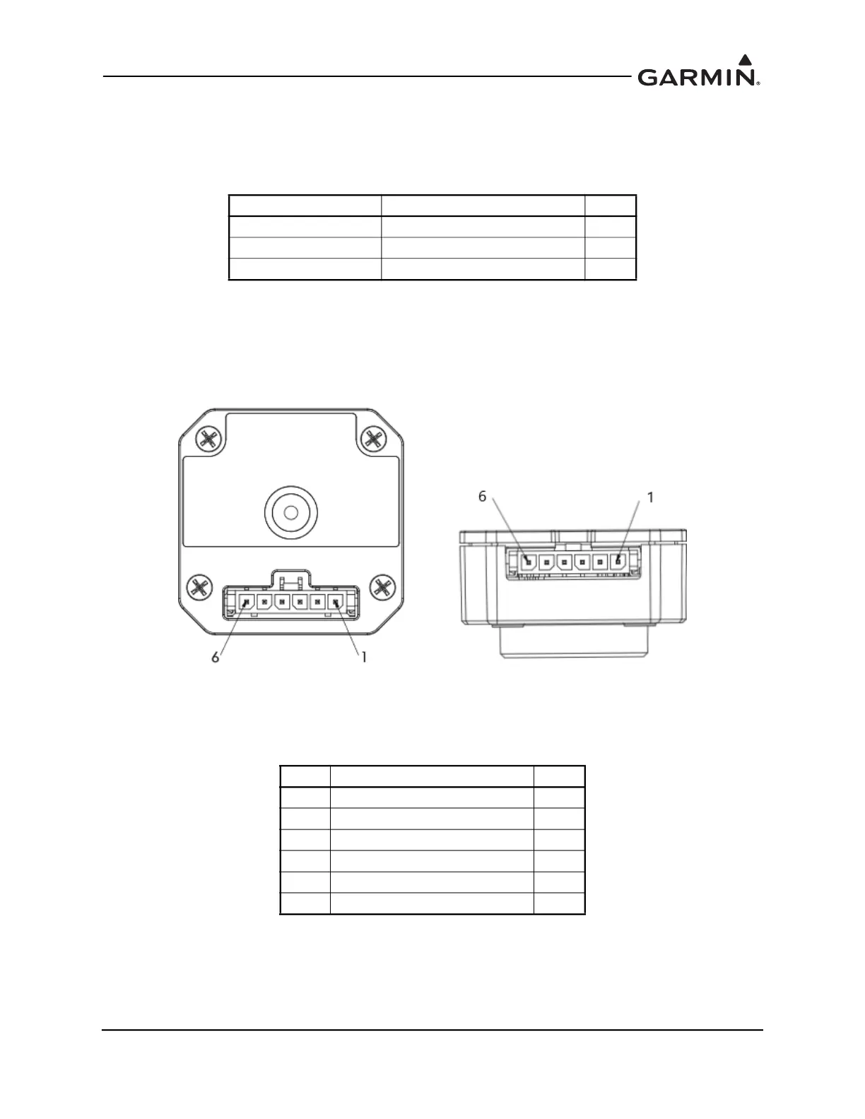
A.7 GSB 15
The GSB 15 has a 6-pin connector in either a vertical or horizontal position. The connector designation
(P201 or P202) is dependent on the part number but the pin numbers and functions are identical (refer to
Table A-17.
Figure A-14 GSB 15 Connectors
Table A-17 J201/P201 & J202/P202
Conductor Color Name I/O
WHITE PROBE POWER LEAD IN
BLUE RESISTIVE ELEMENT HI OUT
ORANGE RESISTIVE ELEMENT LO OUT
Pin Function I/O
1 AIRCRAFT POWER IN
2 USB DN I/O
3 USB DP I/O
4 USB GND --
5 BACKLIGHT ENABLE IN
6 POWER GROUND --
P201, GSB 15 Rear Unit
P/N 011-04937-00/-20/-40
P202, GSB 15 Side Unit
P/N 011-04937-01/-30/-50

 Loading...


