190-02246-10 GI 275 Part 23 AML STC Installation Manual
Rev. 11 Page 3-7
3.2 GI 275 Installation Requirements
This section provides installation requirements for the GI 275 system.
3.2.1 Power Distribution
GI 275 LRUs cannot share circuit breakers or ground return wires with each other or with other equipment.
For the purpose of the GI 275 system installation, the “essential bus” is a bus that receives power when the
battery master is switched on and is not automatically shed with the loss of a generator or alternator. Power
distribution requirements are summarized in Table 3-8.
NOTE
The primary display (i.e., GI 275 Primary ADI or G500/G600 TXi) cannot share a
grounding location with the standby indicator.
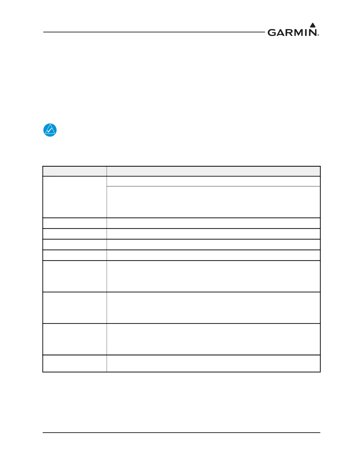
Table 3-8 Power Distribution
LRU BUS Requirement
Primary ADI
• GI 275 with ADAHRS on essential bus
• No. 1 GI 275 with ADAHRS on the essential bus
• No. 2 PFD with ADAHRS on the avionics bus
• If dual essential busses are available, connect No. 2 PFD with ADAHRS to
the separate essential bus
HSI
• Avionics bus
HSI/Standby ADI
• Essential bus
MFD/Standby ADI
• Essential bus
MFD
• Avionics bus
EIS Display
• No. 1 EIS display on essential bus
• No. 2 EIS display on essential bus
• If dual essential busses are available, connect each EIS display to a separate
essential bus
GEA 24
• No. 1 GEA 24 on essential bus
• No. 2 GEA 24 on essential bus
• If dual essential busses are available, connect each GEA 24 to a separate
essential bus
GEA 110
• No. 1 GEA 110 on essential bus
• No. 2 GEA 110 on essential bus
• If dual essential busses are available, connect each GEA 110 to a separate
essential bus. It is acceptable to connect each GEA 110 to both busses
GSB 15
• If connected to a GI 275, connect GSB 15 to same bus as GI 275
• If not connected to GI 275, connect GSB 15 to avionics bus