190-02246-10 GI 275 Part 23 AML STC Installation Manual
Rev. 11 Page 3-5
13. EIS annunciator indicator(s) capable of displaying warning (red) and caution (yellow)
annunciations.
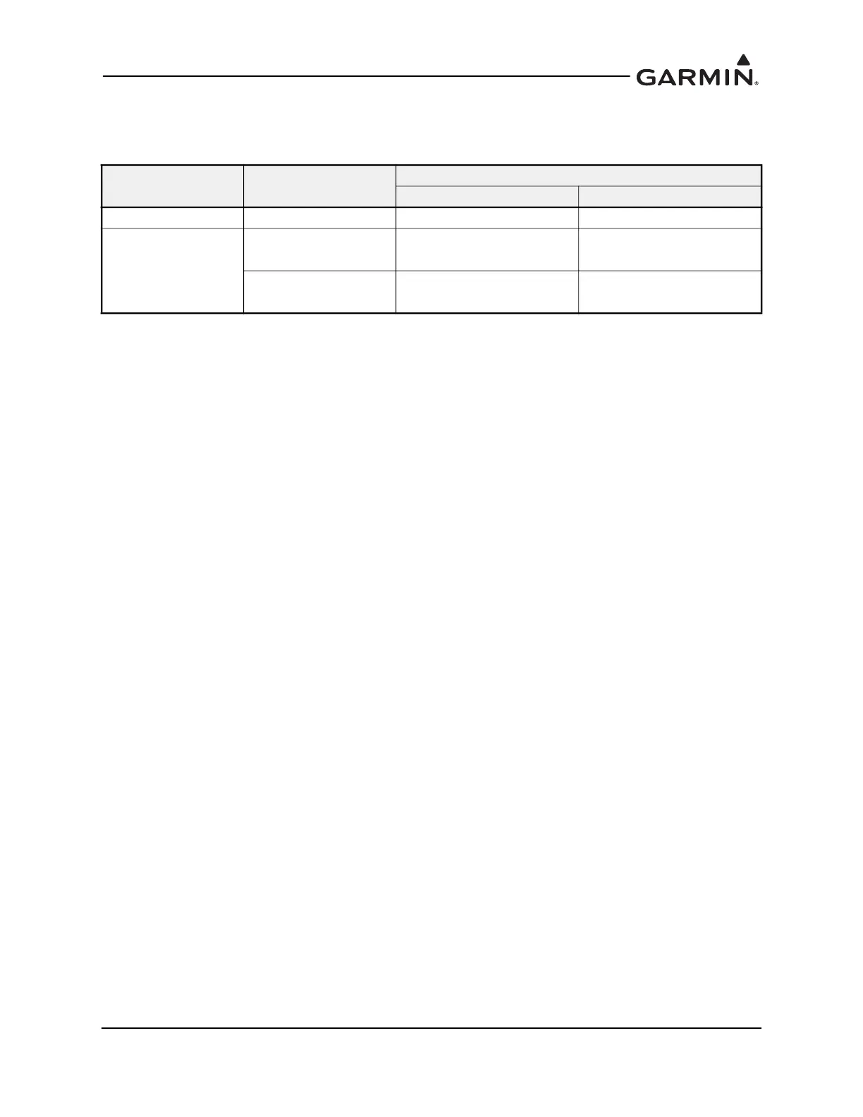
Table 3-6 EIS Annunciator
Notes:
[1] Requires two 47Ω, 1/4 WATT -55 C to +125 C resistors. Refer to Figure B-20.
14. For resistive fuel probe connection with GEA 24 EIS adapter: 2.2k Ω (± 1%), 0.25W (or
greater) resistors qualified to retain power rating at 70 °C and qualified to MIL-R-10509.
Acceptable resistors include:
• RN60D2201FB14 (ref. Garmin Kit P/N 011-05829-00)
• RN60C2201DB14
• RN65E2201FB14
15. Standard heat shrink tubing (M23053/5, X = color)
• M23053/5-104-X for single conductor wire
• M23053/5-105-X for insulating twisted-pair wire
• M23053/5-106-X for insulating triple conductor wire or RG-400 coax
Manufacturer Annunciation
Aircraft System
14V 28V
Applied Avionics Caution/Warning 95-40-17-B4-E1WPN LED-40-17-BA2-E1WP6 [1]
Mil-Spec (Various)
Caution
MS25041-4 Cap
MS25237-330 Lamp
MS25041-4 Cap
MS25237-327 Lamp
Warning
MS25041-2 Cap
MS25237-330 Lamp
MS25041-2 Cap
MS25237-327 Lamp

 Loading...


