190-02246-10 GI 275 Part 23 AML STC Installation Manual
Rev. 11 Page 3-14
3.2.4 GPS Requirements
The GI 275 can be interfaced with up to two independent GPS sources and/or the internal VFR GPS.
Minimum GPS requirements are based on the configuration. Refer to Section 2 for limitations.
Refer to Appendix Section C.4 for approved GPS sources. A GPS source is optional unless the indicator is
internally equipped with an ADAHRS.
3.2.5 Display Lighting Control
Lighting on the GI 275 display can be controlled by either the lighting bus or the built-in photocell. The
photocell can be used for lighting control for all installations.
If there is a significant reduction in lighting bus load due to the GI 275 system installation, it is
recommended that the photocell be used to control the lighting.
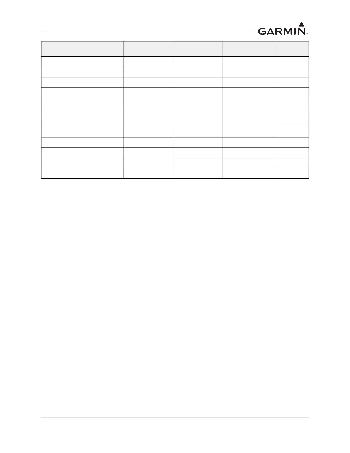
TIT #1 0 – 1800° F Line/Range R, Y, B, G, W °C, °F
TIT #2 0 – 1800° F Line/Range R, Y, B, G, W °C, °F
Carb Temperature -24 – 34° C Line/Range R, Y, B, G, W °C
CDT 32 – 1800° F Line/Range R, Y, B, G, W °C, °F
IAT -100 – 1800° F Line/Range R, Y, B, G, W °C, °F
CDT/IAT Diff Temp -100 – 1800° F
Line/Range
(Max of 2 Ranges)
R, Y, B, G, W °C, °F
Load Meter (alternator current) or
Ammeter (charge/discharge)
-150 – 150 A Line/Range R, Y Amps
Battery Voltage / Bus Voltage -80 – 80 VDC Line/Range R, Y Volts
Prop Sync Wheel N/A N/A N/A N/A
OAT -125 – 175° C N/A N/A °C, °F
Percent Power 0-100% N/A N/A N/A
Display Display Range
Available Gauge
Markings
Available Marking
Colors
Approved
Units

 Loading...


