Operation
50940411/G0219 104 Printed in U.S.A.
Connecting/Disconnecting
Attachments
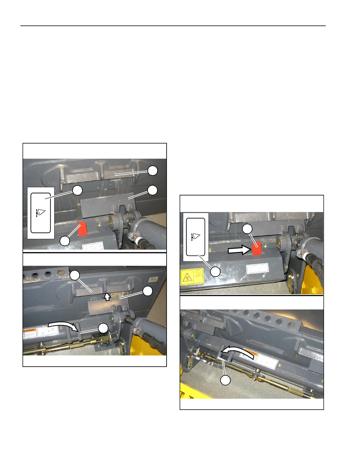
Connecting Attachments
1. Place the attachment lock into the unlocked
position (Fig. 101):
• Power-A-Tach® system hitch – Press the bot-
tom of hitch lock switch (I) until safety flags
(H) have moved all the way in.
• Manual attachment hitch – move hitch lock
lever all the way to the right (G).
2. Tilt the attachment plate forward and drive the
machine straight forward toward the back of the
attachment.
3. Lower the lift arm so tabs (J) on the top of the
attachment plate are aligned just under hooks
(K) on the back of the attachment.
4. Tilt the attachment plate back until tabs (J) on
the top of the attachment plate are engaged
against hooks (K) on the back of the attachment.
5. Raise the lift arm slightly until the attachment is
hanging from hooks (K) and tabs (J) are firmly
inserted into the hooks. Tilt the attachment plate
back, if necessary, so the back of the attachment
is resting flat against the attachment plate.
6. Place the attachment lock into the locked
position (Fig. 102):
• Power-A-Tach® system hitch – Press the top
of hitch lock switch (I) until safety flags (H)
have moved all the way out.
• Manual attachment hitch – Perform the
“Mandatory Safety Shutdown Procedure” on
page 20 and move hitch lock lever all the way
to the left (G).
G
J
K
H
K
J
I
Manual Attachment Hitch In Unlocked Condition
Power-A-Tach® Quick Attach System Hitch In Unlocked
Condition
Fig. 101 – Attachment Hitch – Unlocked
Fig. 102 – Attachment Hitch – Locked
H
I
Power-A-Tach® Quick Attach System Hitch In Locked
Condition
Manual Attachment Hitch In Locked Condition
G
 Loading...