Maintenance
50940411/G0219 152 Printed in U.S.A.
Fuses and Relays
IMPORTANT: Blown fuses indicate electrical sys-
tem malfunctions. Determine what caused the fuse
to blow and repair the problem before replacing the
fuse.
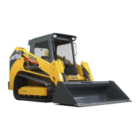
Engine Compartment Fuses/Relays
Model RT250
Fig. 164 – RT250 Fuses – Engine Compartment
A
C
E
B
D
F
G
H
M
N
O
P
Q
R
S
T
U
V
W
X
Y
Z
BB
CC
DD
AA
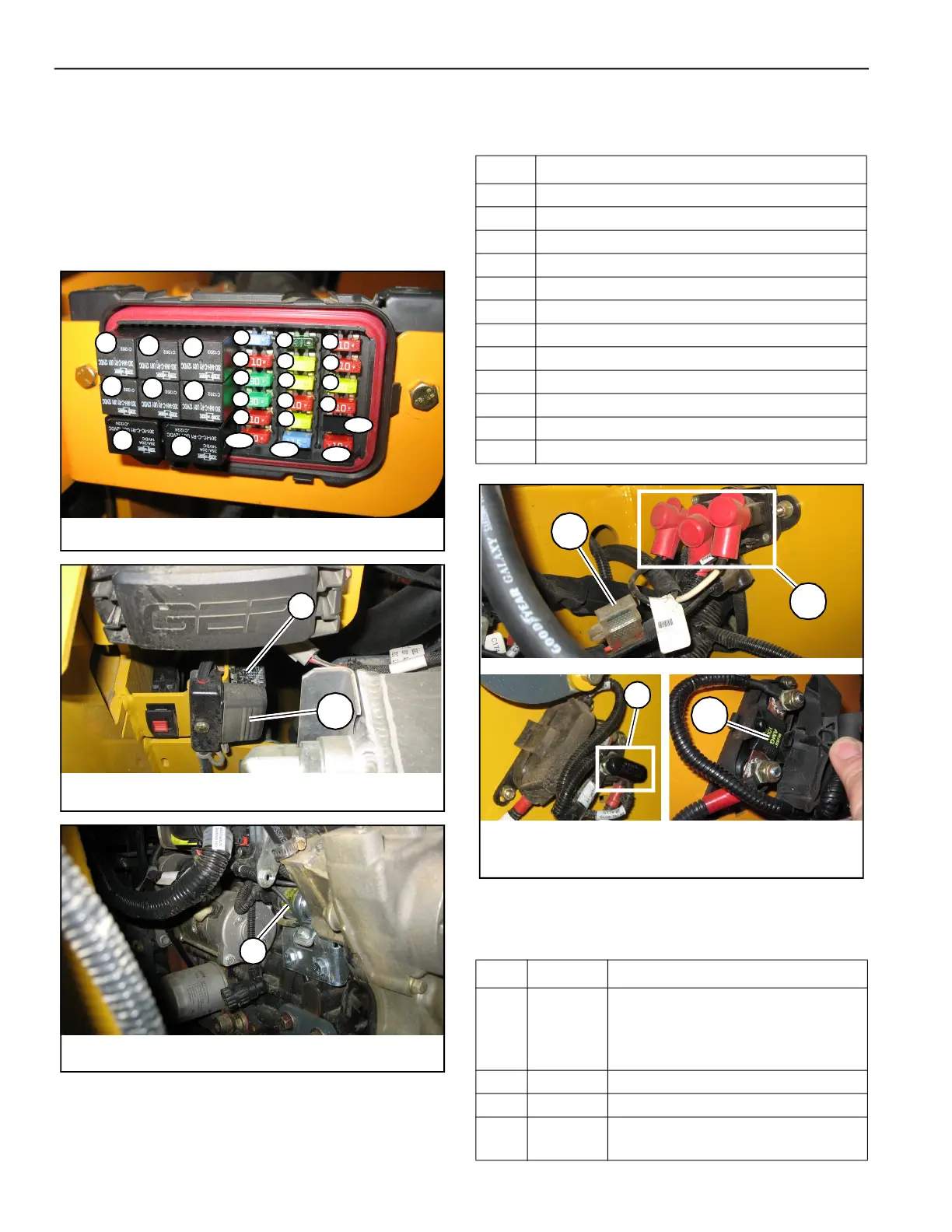
Fig. 165 – RT250 Power Relay, Maxi-Fuse
I
EE
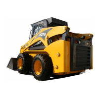
Fig. 166 – RT250 Engine Start Relay
J
Table 39: RT250 (SN 70501 and Up) Engine
Compartment Relays
Relay Circuit
A Horn
B HVAC
C Air Conditioning Condenser Fan
D Work Lights
E Drive, Tilt (Controller 2)
F Wipers
G Parking Brake Switch, Power-A-Tach®
H Fuel Pump
I Power Relay, Ignition Switch, Dome Light
J Engine Start Relay
K Power-A-Tach® Relay
L Glow Relay
Table 40: RT250 (SN 70501 and Up) Engine
Compartment Fuses
Relay Circuit
Fuse
Rated
Current /
Resistance
(A / Ω)
Protected Circuit
M 120Ω CAN Terminating Resistor
N 30A Fuel Pump, Power Splice
O 10A
Power/Relays, Main/Drive Logic Control
Module
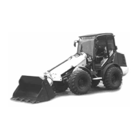
Fig. 167 – RT250 Power-A-Tach®, Glow Relays /
Fuses
FF
GG
K
L
 Loading...